- 您現(xiàn)在的位置:買賣IC網(wǎng) > PDF目錄1961 > PI7C8140AMAE (Pericom)IC PCI-PCI BRIDGE 2PORT 128-QFP PDF資料下載
參數(shù)資料
| 型號: | PI7C8140AMAE |
| 廠商: | Pericom |
| 文件頁數(shù): | 41/82頁 |
| 文件大?。?/td> | 0K |
| 描述: | IC PCI-PCI BRIDGE 2PORT 128-QFP |
| 標(biāo)準(zhǔn)包裝: | 39 |
| 系列: | * |
| 應(yīng)用: | * |
| 接口: | * |
| 電源電壓: | * |
| 封裝/外殼: | 128-BFQFP |
| 供應(yīng)商設(shè)備封裝: | 128-QFP(14x20) |
| 包裝: | 管件 |
| 安裝類型: | 表面貼裝 |
第1頁第2頁第3頁第4頁第5頁第6頁第7頁第8頁第9頁第10頁第11頁第12頁第13頁第14頁第15頁第16頁第17頁第18頁第19頁第20頁第21頁第22頁第23頁第24頁第25頁第26頁第27頁第28頁第29頁第30頁第31頁第32頁第33頁第34頁第35頁第36頁第37頁第38頁第39頁第40頁當(dāng)前第41頁第42頁第43頁第44頁第45頁第46頁第47頁第48頁第49頁第50頁第51頁第52頁第53頁第54頁第55頁第56頁第57頁第58頁第59頁第60頁第61頁第62頁第63頁第64頁第65頁第66頁第67頁第68頁第69頁第70頁第71頁第72頁第73頁第74頁第75頁第76頁第77頁第78頁第79頁第80頁第81頁第82頁

PI7C8140A
2-PORT PCI-TO-PCI BRIDGE
Page 46 of 82
March 20, 2007 – Revision 1.01
The SERR# enable bit is set in the command register.
The parity error response bit is set in the bridge control register of the secondary interface.
The parity error response bit is set in the command register of the primary interface.
Bridge has not detected the parity error on the secondary (initiator) bus, which the parity
error is not forwarded from the secondary bus to the primary bus.
Assertion of P_SERR# is used to signal the parity error condition when the initiator does not know that
the error occurred. Because the data has already been delivered with no errors, there is no other way to
signal this information back to the initiator. If the parity error has forwarded from the initiating bus to
the target bus, P_SERR# will not be asserted.
5.3
DATA PARITY ERROR REPORTING SUMMARY
In the previous sections, the responses of the bridge to data parity errors are presented according to the
type of transaction in progress. This section organizes the responses of the bridge to data parity errors
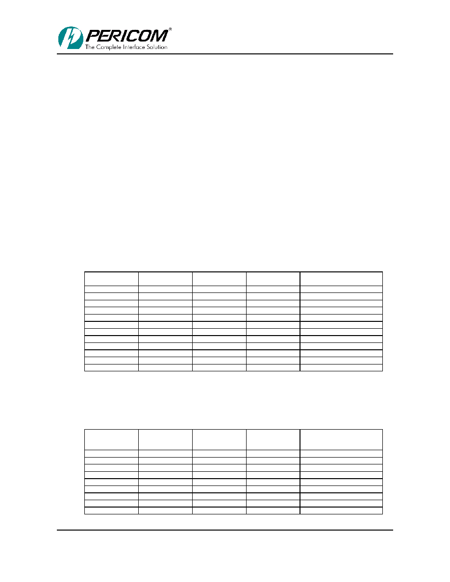
according to the status bits that the bridge sets and the signals that it asserts. Table 5-1 shows setting
the detected parity error bit in the status register, corresponding to the primary interface. This bit is set
when the bridge detects a parity error on the primary interface.
Table 5-1. Setting the Primary Interface Detected Parity Error Bit
Primary Detected
Parity Error Bit
Transaction Type
Direction
Bus Where Error
Was Detected
Primary/ Secondary Parity
Error Response Bits
0
Read
Downstream
Primary
x / x
0
Read
Downstream
Secondary
x / x
1
Read
Upstream
Primary
x / x
0
Read
Upstream
Secondary
x / x
1
Posted Write
Downstream
Primary
x / x
0
Posted Write
Downstream
Secondary
x / x
0
Posted Write
Upstream
Primary
x / x
0
Posted Write
Upstream
Secondary
x / x
1
Delayed Write
Downstream
Primary
x / x
0
Delayed Write
Downstream
Secondary
x / x
0
Delayed Write
Upstream
Primary
x / x
0
Delayed Write
Upstream
Secondary
x / x
X = don’t care
Table 5-2 shows setting the detected parity error bit in the secondary status register, corresponding to
the secondary interface. This bit is set when the bridge detects a parity error on the secondary interface.
Table 5-2. Setting Secondary Interface Detected Parity Error Bit
Secondary
Detected
Parity
Error Bit
Transaction Type
Direction
Bus Where Error
Was Detected
Primary/ Secondary Parity
Error Response Bits
0
Read
Downstream
Primary
x / x
1
Read
Downstream
Secondary
x / x
0
Upstream
Primary
x / x
0
Read
Upstream
Secondary
x / x
0
Posted Write
Downstream
Primary
x / x
0
Posted Write
Downstream
Secondary
x / x
0
Posted Write
Upstream
Primary
x / x
1
Posted Write
Upstream
Secondary
x / x
0
Delayed Write
Downstream
Primary
x / x
07-0067
相關(guān)PDF資料 |
PDF描述 |
|---|---|
| PI7C8150ANDE | IC PCI-PCI BRIDGE 2PORT 256-PBGA |
| PI7C8150BNDIE | IC PCI-PCI BRIDGE ASYNC 256-PBGA |
| PI7C8152BMAIE | IC PCI-PCI BRIDGE 2PORT 160-MQFP |
| PI7C8154ANAE | IC PCI-PCI BRIDGE ASYNC 304-PBGA |
| PI7C8154BNAIE | IC PCI-PCI BRIDGE ASYNC 304-PBGA |
相關(guān)代理商/技術(shù)參數(shù) |
參數(shù)描述 |
|---|---|
| PI7C8148A | 制造商:PERICOM 制造商全稱:Pericom Semiconductor Corporation 功能描述:2-PORT PCI-TO-PCI BRIDGE ADVANCE INFORMATION |
| PI7C8148AEVB | 功能描述:界面開發(fā)工具 64B/66MHz 2 Port PCI Bridge Eval Brd RoHS:否 制造商:Bourns 產(chǎn)品:Evaluation Boards 類型:RS-485 工具用于評估:ADM3485E 接口類型:RS-485 工作電源電壓:3.3 V |
| PI7C8148ANBE | 功能描述:外圍驅(qū)動器與原件 - PCI 2-Port PCI-to-PCI Bridge RoHS:否 制造商:PLX Technology 工作電源電壓: 最大工作溫度: 安裝風(fēng)格:SMD/SMT 封裝 / 箱體:FCBGA-1156 封裝:Tray |
| PI7C8148ANJ | 制造商:PERICOM 制造商全稱:Pericom Semiconductor Corporation 功能描述:2-PORT PCI-TO-PCI BRIDGE ADVANCE INFORMATION |
| PI7C8148ANJE | 功能描述:外圍驅(qū)動器與原件 - PCI 2-Port PCI-to-PCI Bridge RoHS:否 制造商:PLX Technology 工作電源電壓: 最大工作溫度: 安裝風(fēng)格:SMD/SMT 封裝 / 箱體:FCBGA-1156 封裝:Tray |
發(fā)布緊急采購,3分鐘左右您將得到回復(fù)。