- 您現(xiàn)在的位置:買賣IC網(wǎng) > PDF目錄1961 > PI7C8154BNAIE (Pericom)IC PCI-PCI BRIDGE ASYNC 304-PBGA PDF資料下載
參數(shù)資料
| 型號: | PI7C8154BNAIE |
| 廠商: | Pericom |
| 文件頁數(shù): | 24/114頁 |
| 文件大小: | 0K |
| 描述: | IC PCI-PCI BRIDGE ASYNC 304-PBGA |
| 產(chǎn)品變化通告: | Product Discontinuation Notice 22/Jan/2010 |
| 標(biāo)準(zhǔn)包裝: | 27 |
| 系列: | * |
| 應(yīng)用: | * |
| 接口: | * |
| 電源電壓: | * |
| 封裝/外殼: | 304-BBGA |
| 供應(yīng)商設(shè)備封裝: | 304-PBGA(31x31) |
| 包裝: | 管件 |
| 安裝類型: | 表面貼裝 |
第1頁第2頁第3頁第4頁第5頁第6頁第7頁第8頁第9頁第10頁第11頁第12頁第13頁第14頁第15頁第16頁第17頁第18頁第19頁第20頁第21頁第22頁第23頁當(dāng)前第24頁第25頁第26頁第27頁第28頁第29頁第30頁第31頁第32頁第33頁第34頁第35頁第36頁第37頁第38頁第39頁第40頁第41頁第42頁第43頁第44頁第45頁第46頁第47頁第48頁第49頁第50頁第51頁第52頁第53頁第54頁第55頁第56頁第57頁第58頁第59頁第60頁第61頁第62頁第63頁第64頁第65頁第66頁第67頁第68頁第69頁第70頁第71頁第72頁第73頁第74頁第75頁第76頁第77頁第78頁第79頁第80頁第81頁第82頁第83頁第84頁第85頁第86頁第87頁第88頁第89頁第90頁第91頁第92頁第93頁第94頁第95頁第96頁第97頁第98頁第99頁第100頁第101頁第102頁第103頁第104頁第105頁第106頁第107頁第108頁第109頁第110頁第111頁第112頁第113頁第114頁
PI7C8154B
ASYNCHRONOUS 2-PORT
PCI-to-PCI BRIDGE
Advance Information
Page 17 of 112
JUNE 2008 REVISION 1.1
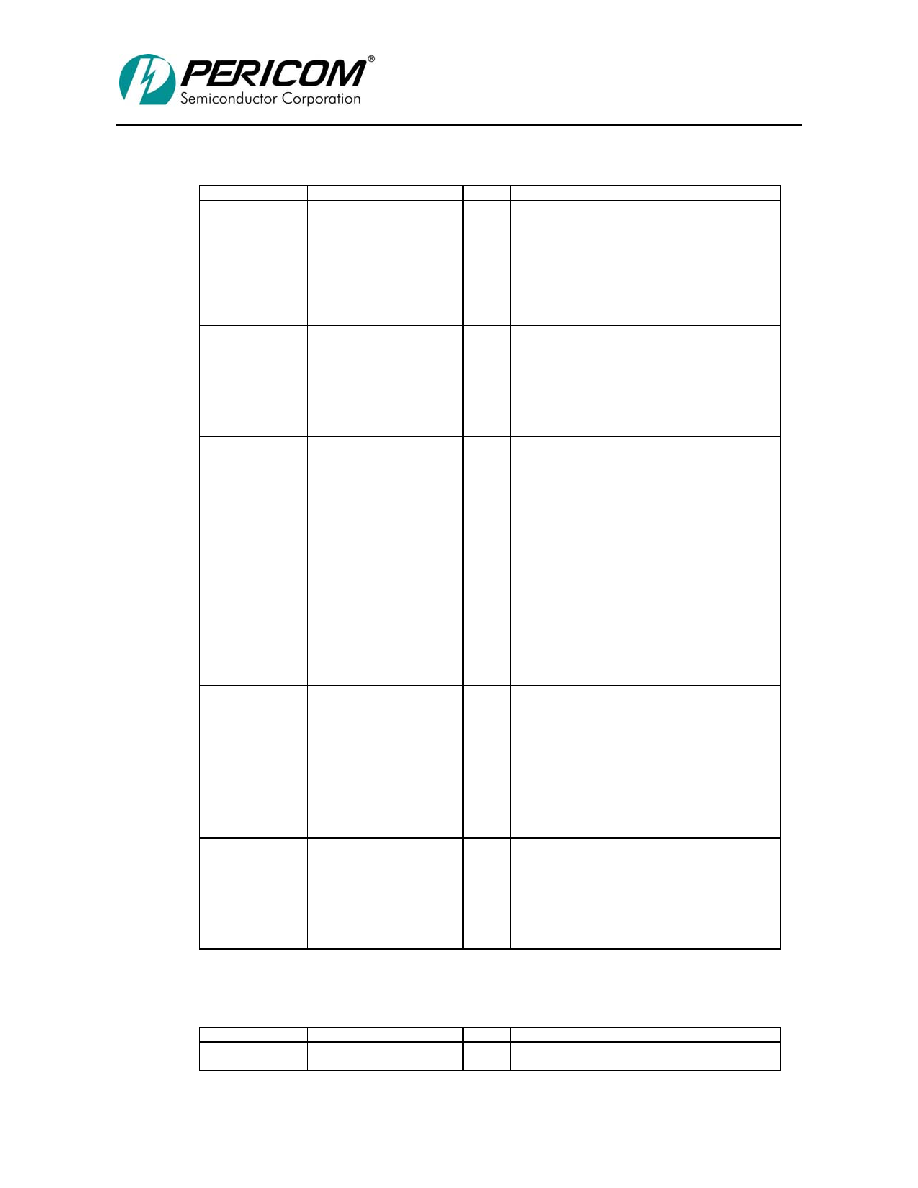
1.2.4
SECONDARY BUS INTERFACE SIGNALS – 64-EXTENSTION
Name
Pin #
Type
Description
S_AD[63:32]
C20, A21, D20, C21, C23,
C22, D21, E20, D22, E21,
E23, F21, F23, F22, G20,
G22, G21, H23, H22, H21,
J23, J20, J22, K23, K22,
K21, L23, L21, L22, M22,
M23, M21
TS
Secondary Upper 32-bit Address/Data:
Multiplexed address and data bus. Address is
indicated by S_FRAME# assertion. Write data is
stable and valid when S_IRDY# is asserted and read
data is stable and valid when S_IRDY# is asserted.
Data is transferred on rising clock edges when both
S_IRDY# and S_TRDY# are asserted. During bus
idle, bridge drives S_AD to a valid logic level when
S_GNT# is asserted respectively.
S_CBE[7:4]
A19, C19, A20, D19
TS
Secondary Upper 32-bit Command/Byte
Enables: Multiplexed command field and byte
enable field. During address phase, the initiator
drives the transaction type on these pins. The
initiator then drives the byte enables during data
phases. During bus idle, bridge drives S_CBE[7:0]
to a valid logic level when the internal grant is
asserted.
S_PAR64
N21
TS
Secondary Upper 32-bit Parity: S_PAR64 carries
the even parity of S_AD[63:32] and S_CBE[7:4] for
both address and data phases. S_PAR64 is driven
by the initiator and is valid 1 cycle after the first
address phase when a dual address command is used
and S_REQ64# is asserted. S_PAR64 is valid 1
clock cycle after the second address phase of a dual
address transaction when S_REQ64# is asserted.
S_PAR64 is valid 1 cycle after valid data is driven
when both S_REQ64# and S_ACK64# are asserted
for that data phase. S_PAR64 is driven by the
device driving read or write data 1 cycle after the
S_AD lines are driven. S_PAR64 is tri-stated 1
cycle after the S_AD lines are tri-stated. Devices
receive data sample S_PAR64 as an input to check
for possible parity errors during 64-bit transactions.
When not driven, S_PAR64 is pulled up to a valid
logic level through external resistors.
S_REQ64#
B19
STS
Secondary 64-bit Transfer Request: S_REQ64#
is asserted by the initiator to indicate that the
initiator is requesting a 64-bit data transfer.
S_REQ64# has the same timing as S_FRAME#.
When S_REQ64# is asserted LOW during reset, a
64-bit data path is supported. When S_REQ64# is
HIGH during reset, bridge drives S_AD[63:32],
S_CBE[7:4], and S_PAR64 to valid logic levels.
When deasserting, S_REQ64# is driven to a
deasserted state for 1 cycle and then sustained by an
external pull-up resistor.
S_ACK64#
C18
STS
Secondary 64-bit Transfer Acknowledge:
S_ACK64# is asserted by the target only when
S_REQ64# is asserted by the initiator to indicate the
target’s ability to transfer data using 64 bits.
S_ACK64# has the same timing as S_DEVSEL#.
When deasserting, S_ACK64# is driven to a
deasserted state for 1 cycle and then is sustained by
an external pull-up resistor.
1.2.5
CLOCK SIGNALS
Name
Pin #
Type
Description
P_CLK
T3
I
Primary Clock Input: Provides timing for all
transactions on the primary interface.
相關(guān)PDF資料 |
PDF描述 |
|---|---|
| PI7C9X110BNBE | IC PCIE TO PCI REV BRG 160LFBGA |
| PI7C9X130DNDE | IC PCIE-PCIX BRIDGE 1PORT 256BGA |
| PI7C9X20303SLCFDE | IC PCIE PACKET SWITCH 128LQFP |
| PI7C9X20303ULAZPE | IC PCIE PACKET SWITCH 132TQFN |
| PI7C9X20404GPBNBE | IC PCIE PACKET SWITCH 148LFBGA |
相關(guān)代理商/技術(shù)參數(shù) |
參數(shù)描述 |
|---|---|
| PI7C8154EVB | 功能描述:界面開發(fā)工具 64B/66MHz 2 Port PCI Bridge Eval Brd RoHS:否 制造商:Bourns 產(chǎn)品:Evaluation Boards 類型:RS-485 工具用于評估:ADM3485E 接口類型:RS-485 工作電源電壓:3.3 V |
| PI7C8154NA-33 | 制造商:PERICOM 功能描述: |
| PI7C81552 | 制造商:PERICOM 制造商全稱:Pericom Semiconductor Corporation 功能描述:ENHANCED 2-PORT PCI TO PCI BRIDGE INTEL 21152 COMPARISON |
| PI7C81552A | 制造商:PERICOM 制造商全稱:Pericom Semiconductor Corporation 功能描述:ENHANCED 2-PORT PCI TO PCI BRIDGE INTEL 21152 COMPARISON |
| PI7C9X110 | 制造商:PERICOM 制造商全稱:Pericom Semiconductor Corporation 功能描述:PCI Express-to-PCI Reversible Bridge |
發(fā)布緊急采購,3分鐘左右您將得到回復(fù)。