- 您現(xiàn)在的位置:買賣IC網(wǎng) > PDF目錄379802 > CD1283 (Intel Corp.) IEEE 1284-Compatible Parallel Interface PDF資料下載
參數(shù)資料
| 型號(hào): | CD1283 |
| 廠商: | Intel Corp. |
| 英文描述: | IEEE 1284-Compatible Parallel Interface |
| 中文描述: | 符合IEEE 1284兼容并行接口 |
| 文件頁數(shù): | 62/94頁 |
| 文件大小: | 1237K |
| 代理商: | CD1283 |
第1頁第2頁第3頁第4頁第5頁第6頁第7頁第8頁第9頁第10頁第11頁第12頁第13頁第14頁第15頁第16頁第17頁第18頁第19頁第20頁第21頁第22頁第23頁第24頁第25頁第26頁第27頁第28頁第29頁第30頁第31頁第32頁第33頁第34頁第35頁第36頁第37頁第38頁第39頁第40頁第41頁第42頁第43頁第44頁第45頁第46頁第47頁第48頁第49頁第50頁第51頁第52頁第53頁第54頁第55頁第56頁第57頁第58頁第59頁第60頁第61頁當(dāng)前第62頁第63頁第64頁第65頁第66頁第67頁第68頁第69頁第70頁第71頁第72頁第73頁第74頁第75頁第76頁第77頁第78頁第79頁第80頁第81頁第82頁第83頁第84頁第85頁第86頁第87頁第88頁第89頁第90頁第91頁第92頁第93頁第94頁

CD1283
—
IEEE 1284-Compatible Parallel Interface
62
Datasheet
This register can be used to issue a hardware reset to the parallel channel
.
7.3.8
Parallel FIFO Control Register
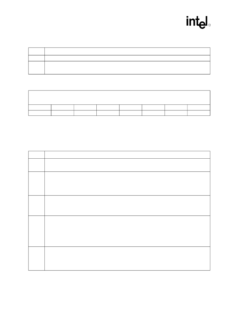
This register controls overall function of the parallel FIFO. These include resetting (flushing) the
FIFO, enabling DMA transfers, enabling host interrupts, run-length encoding, and so on. The host
sets these bits according to the mode of operation desired.
After hard reset (either through the RESET* input pin or by setting bit 0 in the PCRR), this register
is cleared to all zeroes.
Bit
Description
7:1
These bits are not used and must always be
‘
0
’
.
0
PChReset:
When this bit is set, it asserts the equivalent of a hardware power-on reset to the parallel channel,
Channel 0. If set by the host, PChReset must be cleared to resume normal parallel channel operation. This hardware
reset affects
only
the parallel channel and has no effect on other functions of the device.
Register Name: PFCR
Register Description: Parallel FIFO Control
Access: R/W
8-Bit Hex Address: 31
Default Value: 00
Bit 7
Bit 6
Bit 5
Bit 4
Bit 3
Bit 2
Bit 1
Bit 0
FIFOres
DMAen
DMAdir
IntEn
RLEen
setTAG
ErrEn
DMAbufWe
Bit
Description
(Sheet 1 of 2)
7
FIFO Reset:
This bit must be set together with the correct value of DMAdir to properly initialize the data pipeline and
FIFO registers for data transfer or when a new data transfer direction is desired. Data remaining in the FIFO is
discarded.
6
DMA Enable:
This bit must be set for DMA requests to move data to/from the FIFO. When DMAen is set to
‘
1
’
, the
PFQR quantity value is compared with the PFTR user-programmed threshold value. In Receive mode, if the
threshold is equalled or exceeded, DMAREQ* is asserted to cause DMA data transfers of whole (2-byte) words from
the FIFO through the data pipeline. In Transmit mode, if the amount of data in the FIFO is equal or less than the
threshold, DMAREQ* is asserted to cause DMA data transfers of whole (2-byte) words to the FIFO through the data
pipeline.
5
DMA Direction:
This bit sets the direction of transfer between the parallel FIFO and system memory. If DMAdir is set
to
‘
1
’
, the direction is transmit (system memory to the parallel FIFO); if it is
‘
0
’
the direction is receive. The desired
DMAdir value must be set together with FIFOres when initializing the FIFO logic for data transfer. Once a DMAdir
value is set and the FIFOres is complete, that DMAdir selection must be maintained during any other changes to the
control bits of the PFCR.
4
Interrupt Enable:
This is the master interrupt enable for the parallel channel. This bit must be set for any interrupts
to be generated by the data pipeline, parallel port, or error status. In Poll-mode operation, host software may toggle
this bit to signal the completion of the service-acknowledge cycle and clear the current status in the PIR, SVRR, and
LIVR. Toggling this bit updates the state of SVCREQP* and the PIR according to the current state of PCISR, DERR
and PFSR. For this reason, PCISR, DERR, and PFSR should be read and cleared at the beginning of the service
routine. These registers should be checked again at the end of the service routine to ensure that no requests were
skipped because an edge-sensitive interrupt controller may not detect a request that is already active when the
program returns from the service routine.
3
RLE Enable:
This bit enables run-length encoding/decoding for direction defined by DMAdir. The RLEen bit affects
the flow of data through the data pipeline in the transmit direction. Data flow into the FIFO is managed in so that the
PFHR1 and PFHR2 are kept full to permit evaluation of data sequences for possible compression. The effect is that
following any data transfer while RLEen is set, the final 2 bytes written to the DMABUF register are kept in PFHR1
and PFHR2. To allow these bytes to be moved into the FIFO or to make room in PFHR1 for a tagged data transfer,
RLEen must be
‘
0
’
and both DMAen and DMAbufWe must be
‘
0
’
.
相關(guān)PDF資料 |
PDF描述 |
|---|---|
| CD1284 | IEEE 1284-Compatible Parallel Interface Controller with Two High-Speed Asynchronous Serial Ports |
| CD13002 | NPN SILICON PLANAR EPITAXIAL, HIGH VOLTAGE FAST SWITCHING POWER TRANSISTOR |
| CD14538 | CMOS DUAL PRECISION MONOSTABLE MULTIVIBRATOR |
| CD14538BMS | CMOS Dual Precision Monostable Multivibrator |
| CD15B-15MB | CD105B |
相關(guān)代理商/技術(shù)參數(shù) |
參數(shù)描述 |
|---|---|
| CD1284 | 制造商:INTEL 制造商全稱:Intel Corporation 功能描述:IEEE 1284-Compatible Parallel Interface Controller with Two High-Speed Asynchronous Serial Ports |
| CD-12AFFM-QL8D01 | 功能描述:MIDDLE 制造商:amphenol ltw 系列:* 零件狀態(tài):在售 標(biāo)準(zhǔn)包裝:10 |
| CD-12AFFM-QR8D01 | 功能描述:MIDDLE 制造商:amphenol ltw 系列:* 零件狀態(tài):在售 標(biāo)準(zhǔn)包裝:10 |
| CD-12AMMM-QL8D01 | 功能描述:MIDDLE 制造商:amphenol ltw 系列:* 零件狀態(tài):在售 標(biāo)準(zhǔn)包裝:10 |
| CD-12BFFA-LL7001 | 功能描述:MIDDLE 制造商:amphenol ltw 系列:* 零件狀態(tài):在售 標(biāo)準(zhǔn)包裝:10 |
發(fā)布緊急采購,3分鐘左右您將得到回復(fù)。