- 您現在的位置:買賣IC網 > PDF目錄379802 > CD1283 (Intel Corp.) IEEE 1284-Compatible Parallel Interface PDF資料下載
參數資料
| 型號: | CD1283 |
| 廠商: | Intel Corp. |
| 英文描述: | IEEE 1284-Compatible Parallel Interface |
| 中文描述: | 符合IEEE 1284兼容并行接口 |
| 文件頁數: | 57/94頁 |
| 文件大小: | 1237K |
| 代理商: | CD1283 |
第1頁第2頁第3頁第4頁第5頁第6頁第7頁第8頁第9頁第10頁第11頁第12頁第13頁第14頁第15頁第16頁第17頁第18頁第19頁第20頁第21頁第22頁第23頁第24頁第25頁第26頁第27頁第28頁第29頁第30頁第31頁第32頁第33頁第34頁第35頁第36頁第37頁第38頁第39頁第40頁第41頁第42頁第43頁第44頁第45頁第46頁第47頁第48頁第49頁第50頁第51頁第52頁第53頁第54頁第55頁第56頁當前第57頁第58頁第59頁第60頁第61頁第62頁第63頁第64頁第65頁第66頁第67頁第68頁第69頁第70頁第71頁第72頁第73頁第74頁第75頁第76頁第77頁第78頁第79頁第80頁第81頁第82頁第83頁第84頁第85頁第86頁第87頁第88頁第89頁第90頁第91頁第92頁第93頁第94頁

IEEE 1284-Compatible Parallel Interface
—
CD1283
Datasheet
57
7.3
Parallel Pipeline Registers
7.3.1
Data Error Register
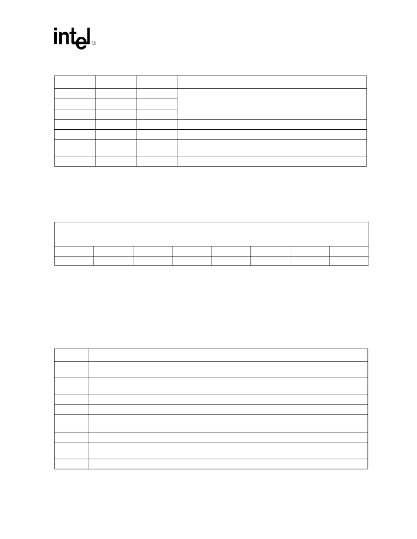
The bits in this read-only register indicate read/write errors involving the DMA Buffer register and
the Data Pipeline registers. The DataErr bit in PFSR is the logical OR of these eight Error Status
bits.
A read of this register has no effect on the error status. A write to this register clears all bits; they
are not individually writable by the user. Host software should clear this register (write x
’
00) after
completing an error service-acknowledge procedure. This bit is provided primarily as an aid to
driver software development. Under normal circumstances, data errors should never occur. This
register is cleared during device reset.
0
0
1
Invalid.
0
1
1
1
0
0
The parallel channel state machine requests service.
1
0
1
The parallel channel data pipeline requests service.
1
1
0
Both the parallel port state machine and the parallel port data pipeline
request service.
1
1
1
Invalid.
Table 10. PIVR[2:0] Encoding
IT2
IT1
IT0
Description
Register Name: DER
Register Description: Data Error
Access: Read only
8-Bit Hex Address: 33
Default Value: 00
Bit 7
Bit 6
Bit 5
Bit 4
Bit 3
Bit 2
Bit 1
Bit 0
DMAwrerr
DMArderr
Bufwrerr
Bufrderr
HR1wrerr
HR1rderr
HR2wrerr
HR2rderr
Bit
Description
7
DMA Write Error:
This bit is set if the DMA control logic has written to the DMA buffer when it already contains
data. It indicates that an invalid DMA transfer cycle occurred (a DMAACK* without a corresponding DMAREQ*).
6
DMA Read Error:
As with bit 7, this bit indicates that DMA logic has performed a read from the DMA Buffer when
there was no data in it. It indicates that an invalid DMA transfer cycle occurred.
5
Buffer Write Error:
This bit indicates that a system write to the DMA buffer occurred while it still contained data.
4
Buffer Read Error:
This bit indicates that a system read from the DMA buffer occurred while it was empty.
3
Holding Register 1 Write Error:
This bit indicates that a system write to PFHR1 (Parallel FIFO Hold-
ing register 1) occurred while it still contained data.
2
Holding Register 1 Read Error:
This bit indicates that a system read from PFHR1 occurred while it was empty.
1
Holding Register 2 Write Error:
This bit indicates that a system write to PFHR2 (Parallel FIFO Holding register 2)
occurred while it still contained data.
0
Holding Register 2 Read Error:
This bit indicates that a system read from PFHR2 occurred while it was empty.
相關PDF資料 |
PDF描述 |
|---|---|
| CD1284 | IEEE 1284-Compatible Parallel Interface Controller with Two High-Speed Asynchronous Serial Ports |
| CD13002 | NPN SILICON PLANAR EPITAXIAL, HIGH VOLTAGE FAST SWITCHING POWER TRANSISTOR |
| CD14538 | CMOS DUAL PRECISION MONOSTABLE MULTIVIBRATOR |
| CD14538BMS | CMOS Dual Precision Monostable Multivibrator |
| CD15B-15MB | CD105B |
相關代理商/技術參數 |
參數描述 |
|---|---|
| CD1284 | 制造商:INTEL 制造商全稱:Intel Corporation 功能描述:IEEE 1284-Compatible Parallel Interface Controller with Two High-Speed Asynchronous Serial Ports |
| CD-12AFFM-QL8D01 | 功能描述:MIDDLE 制造商:amphenol ltw 系列:* 零件狀態(tài):在售 標準包裝:10 |
| CD-12AFFM-QR8D01 | 功能描述:MIDDLE 制造商:amphenol ltw 系列:* 零件狀態(tài):在售 標準包裝:10 |
| CD-12AMMM-QL8D01 | 功能描述:MIDDLE 制造商:amphenol ltw 系列:* 零件狀態(tài):在售 標準包裝:10 |
| CD-12BFFA-LL7001 | 功能描述:MIDDLE 制造商:amphenol ltw 系列:* 零件狀態(tài):在售 標準包裝:10 |
發(fā)布緊急采購,3分鐘左右您將得到回復。