- 您現(xiàn)在的位置:買賣IC網(wǎng) > PDF目錄383876 > T7698 (Lineage Power) Quad T1/E1 Line Interface and Octal T1/E1 Monitor(四T1/E1線接口和八T1/E1監(jiān)控器) PDF資料下載
參數(shù)資料
| 型號(hào): | T7698 |
| 廠商: | Lineage Power |
| 英文描述: | Quad T1/E1 Line Interface and Octal T1/E1 Monitor(四T1/E1線接口和八T1/E1監(jiān)控器) |
| 中文描述: | 四T1/E1線路接口和八路的T1/E1監(jiān)視器(四個(gè)T1/E1線接口和八T1/E1的監(jiān)控器) |
| 文件頁(yè)數(shù): | 96/112頁(yè) |
| 文件大小: | 1359K |
| 代理商: | T7698 |
第1頁(yè)第2頁(yè)第3頁(yè)第4頁(yè)第5頁(yè)第6頁(yè)第7頁(yè)第8頁(yè)第9頁(yè)第10頁(yè)第11頁(yè)第12頁(yè)第13頁(yè)第14頁(yè)第15頁(yè)第16頁(yè)第17頁(yè)第18頁(yè)第19頁(yè)第20頁(yè)第21頁(yè)第22頁(yè)第23頁(yè)第24頁(yè)第25頁(yè)第26頁(yè)第27頁(yè)第28頁(yè)第29頁(yè)第30頁(yè)第31頁(yè)第32頁(yè)第33頁(yè)第34頁(yè)第35頁(yè)第36頁(yè)第37頁(yè)第38頁(yè)第39頁(yè)第40頁(yè)第41頁(yè)第42頁(yè)第43頁(yè)第44頁(yè)第45頁(yè)第46頁(yè)第47頁(yè)第48頁(yè)第49頁(yè)第50頁(yè)第51頁(yè)第52頁(yè)第53頁(yè)第54頁(yè)第55頁(yè)第56頁(yè)第57頁(yè)第58頁(yè)第59頁(yè)第60頁(yè)第61頁(yè)第62頁(yè)第63頁(yè)第64頁(yè)第65頁(yè)第66頁(yè)第67頁(yè)第68頁(yè)第69頁(yè)第70頁(yè)第71頁(yè)第72頁(yè)第73頁(yè)第74頁(yè)第75頁(yè)第76頁(yè)第77頁(yè)第78頁(yè)第79頁(yè)第80頁(yè)第81頁(yè)第82頁(yè)第83頁(yè)第84頁(yè)第85頁(yè)第86頁(yè)第87頁(yè)第88頁(yè)第89頁(yè)第90頁(yè)第91頁(yè)第92頁(yè)第93頁(yè)第94頁(yè)第95頁(yè)當(dāng)前第96頁(yè)第97頁(yè)第98頁(yè)第99頁(yè)第100頁(yè)第101頁(yè)第102頁(yè)第103頁(yè)第104頁(yè)第105頁(yè)第106頁(yè)第107頁(yè)第108頁(yè)第109頁(yè)第110頁(yè)第111頁(yè)第112頁(yè)
Data Sheet
January 1999
T7698 Quad T1/E1 Line Interface and Octal T1/E1 Monitor
96
Lucent Technologies Inc.
Facility Data Links
(continued)
Facility Data Link Parameter/Status Registers
(continued)
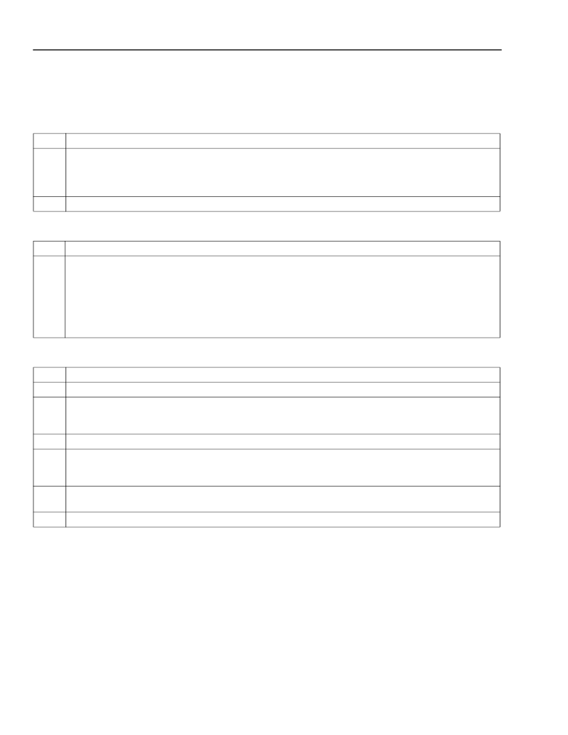
Table 102. FDL Receiver Fill Level Control Register (FDL_PR1)
Table 103. FDL Receiver Match Character Register (FDL_PR2)
Table 104. FDL Transparent Mode Control Register (FDL_PR3)
Bits
0—5
Description
Receive Fill Level (RFL[0:5]).
Bits 0—5 define the receive FIFO full threshold value that will cause the
receive FIFO fill (RF) status bit to be set. RFL = 00000 forces the receive FIFO to set the RF bit when the
receive FIFO is completely full. RFL = 01111 will force the receive FIFO to set the RF bit when the receive
FIFO contains 15 or more bytes.
Reserved.
6—7
Bits
0—7
Description
Receiver Match Character (RHMC0—RHMC7).
This character is used only in the transparent mode
(register FDL_PR3, bit 6 = 1). When the pattern match bit (register FDL_PR3, bit 5) is set to 1, the
receiver searches the incoming bit stream for the receiver match character. Data is loaded into the receive
FIFO only after this character has been identified. The byte identified as matching the receiver match
character is the first byte loaded into the FIFO. The default is to search for an HDLC flag, but any charac-
ter can be programmed by the user. The search for the receive match character is in a sliding window
fashion.
Bits
0—2
3
Description
Reserved.
Match Status (MSTAT).
Read only. When this bit is set to 1, the receiver match character has been rec-
ognized. If no match is being performed (register FDL_PR3, bit 5 = 0), the MSTAT bit is set to 1 automat-
ically when the first bit is received.
Reserved.
Should be set to 0.
Pattern Match (MATCH).
When this bit is set to 1, the FDL receiver does not load the data into the
receive FIFO until the receive match character has been detected. When this bit is 0, the receiver loads
the data into the receive FIFO without searching for a match character.
FDL Transparent Mode (HTRANS).
When this bit is set to 1, the FDL receiver performs no HDLC pro-
cessing on incoming data.
FDL Test.
This bit is reserved for manufacturing test purposes only and should be set to 0.
4
5
6
7
相關(guān)PDF資料 |
PDF描述 |
|---|---|
| T7705A | SUPPLY-VOLTAGE SUPERVISORS |
| T8100A | H.100/H.110 Interface and Time-Slot Interchanger(H.100/H.110接口和干線時(shí)間段交換機(jī)) |
| T8100 | H.100/H.110 Interface and Time-Slot Interchanger(H.100/H.110接口和干線時(shí)隙交換機(jī)) |
| T8102 | H.100/H.110 Interface and Time-Slot Interchanger(H.100/H.110接口和干線時(shí)隙交換機(jī)) |
| T8105 | H.100/H.110 Interface and Time-Slot Interchanger(H.100/H.110接口和干線時(shí)隙交換機(jī)) |
相關(guān)代理商/技術(shù)參數(shù) |
參數(shù)描述 |
|---|---|
| T77 | 制造商:Thomas & Betts 功能描述:2-1/2"CONDUIT BODY,IRON,T,F-7 制造商:Cooper Crouse-Hinds 功能描述: 制造商:Thomas & Betts 功能描述:Fittings T-Fitting 2.5inch Non-Thread Iron |
| T7700 | 制造商:INTEL 制造商全稱:Intel Corporation 功能描述:Core2 Duo Processors and Core2 Extreme Processors for Platforms Based on Mobile 965 Express Chipset Family |
| T77000150 | 制造商:Assembly Value Added 功能描述: |
| T7705102CA | 制造商:Texas Instruments 功能描述: |
| T7705A | 制造商:TI 制造商全稱:Texas Instruments 功能描述:SUPPLY-VOLTAGE SUPERVISORS |
發(fā)布緊急采購(gòu),3分鐘左右您將得到回復(fù)。