- 您現(xiàn)在的位置:買賣IC網(wǎng) > PDF目錄383876 > T7698 (Lineage Power) Quad T1/E1 Line Interface and Octal T1/E1 Monitor(四T1/E1線接口和八T1/E1監(jiān)控器) PDF資料下載
參數(shù)資料
| 型號(hào): | T7698 |
| 廠商: | Lineage Power |
| 英文描述: | Quad T1/E1 Line Interface and Octal T1/E1 Monitor(四T1/E1線接口和八T1/E1監(jiān)控器) |
| 中文描述: | 四T1/E1線路接口和八路的T1/E1監(jiān)視器(四個(gè)T1/E1線接口和八T1/E1的監(jiān)控器) |
| 文件頁數(shù): | 92/112頁 |
| 文件大小: | 1359K |
| 代理商: | T7698 |
第1頁第2頁第3頁第4頁第5頁第6頁第7頁第8頁第9頁第10頁第11頁第12頁第13頁第14頁第15頁第16頁第17頁第18頁第19頁第20頁第21頁第22頁第23頁第24頁第25頁第26頁第27頁第28頁第29頁第30頁第31頁第32頁第33頁第34頁第35頁第36頁第37頁第38頁第39頁第40頁第41頁第42頁第43頁第44頁第45頁第46頁第47頁第48頁第49頁第50頁第51頁第52頁第53頁第54頁第55頁第56頁第57頁第58頁第59頁第60頁第61頁第62頁第63頁第64頁第65頁第66頁第67頁第68頁第69頁第70頁第71頁第72頁第73頁第74頁第75頁第76頁第77頁第78頁第79頁第80頁第81頁第82頁第83頁第84頁第85頁第86頁第87頁第88頁第89頁第90頁第91頁當(dāng)前第92頁第93頁第94頁第95頁第96頁第97頁第98頁第99頁第100頁第101頁第102頁第103頁第104頁第105頁第106頁第107頁第108頁第109頁第110頁第111頁第112頁
Data Sheet
January 1999
T7698 Quad T1/E1 Line Interface and Octal T1/E1 Monitor
92
Lucent Technologies Inc.
Facility Data Links
(continued)
FDL Features
(continued)
HDLC Mode
The receive queue manager forms a status of frame (SF) byte for each HDLC frame and stores the SF byte in the
receive FDL FIFO after the last data byte of the associated frame. HDLC frames with n bytes will have (n + 1) bytes
stored in the receive FIFO. The frame check sequence (CRC) bytes of the received HDLC frame are not stored into
the receive FIFO, unless the HRPF bit (register FDL_PR0, bit 2) is set (i.e., HDLC mode with PRM is enabled).
The SF byte has the following format.
Whenever an SF byte is present in the FIFO, the end of frame (EOF) bit (register FDL_SR1, FDL bit 7) is set. The
receiver queue status (RQS) bits (register FDL_SR1, bits 0—6) report the number of bytes up to and including the
first SF byte. If no SF byte is present in the FIFO, the count directly reflects the number of data bytes available to be
read. Depending on the FDL frame size, it is possible for multiple frames to be present in the FIFO. The receive fill
level (RFL) indicator (register FDL_PR1, bits 0—5) can be programmed in the receive FDL control register to tailor
the service time interval to the system environment. The FIFO full (RF) status bit (register FDL_SR0, bit 0) is set in
the status register when the FIFO reaches the preprogrammed full position. In the HDLC mode, REOF status bit
(register FDL_SR0, bit 1) is set high when the receiver has identified the end of frame and has written the SF byte
for that frame. The FDL overrun status bit (register FDL_SR0, bit 2) is set high when the receiver needs to write
either status or data to the FIFO when the FIFO is full. An overrun condition will cause the last byte of the FIFO to
be overwritten with an SF byte indicating the overrun status. In the HDLC mode, the receive idle (RIDL) status bit
(register FDL_SR0, bit 3) is set high whenever 15 or more continuous 1s have been detected.
Transparent Mode
The receive FIFO receives FDL data from the receive frame monitor and directly loads this FDL information bit for
bit, least significant bit first. If the MATCH bit is set in the FDL control register, the receive FDL FIFO will load data
only after the matched pattern has been detected. The match character and all subsequent bytes are placed into
the receive FIFO.
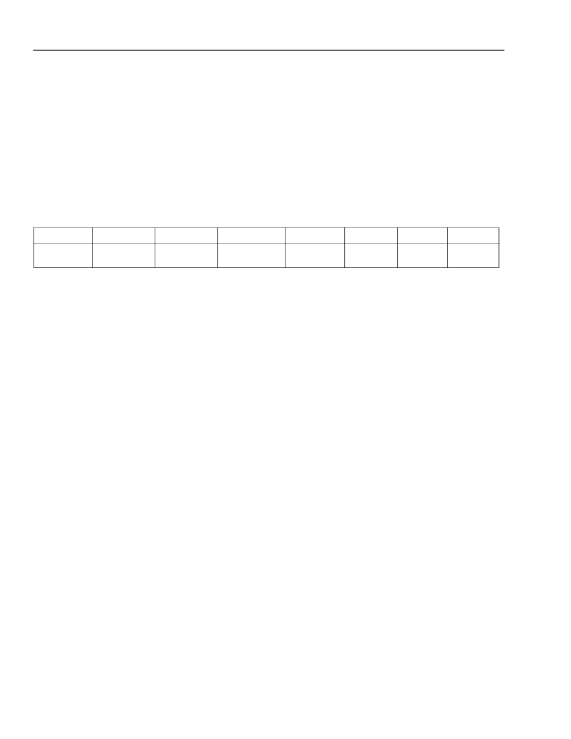
Table 98. HDLC Status of Frame Byte
RSF B7
BAD CRC
RSF B6
ABORT
RSF B5
FIFO
OVERRUN
RSF B4
BAD BYTE
COUNT
RSF B3
0
RSF B2
0
RSF B1
0
RSF B0
0
相關(guān)PDF資料 |
PDF描述 |
|---|---|
| T7705A | SUPPLY-VOLTAGE SUPERVISORS |
| T8100A | H.100/H.110 Interface and Time-Slot Interchanger(H.100/H.110接口和干線時(shí)間段交換機(jī)) |
| T8100 | H.100/H.110 Interface and Time-Slot Interchanger(H.100/H.110接口和干線時(shí)隙交換機(jī)) |
| T8102 | H.100/H.110 Interface and Time-Slot Interchanger(H.100/H.110接口和干線時(shí)隙交換機(jī)) |
| T8105 | H.100/H.110 Interface and Time-Slot Interchanger(H.100/H.110接口和干線時(shí)隙交換機(jī)) |
相關(guān)代理商/技術(shù)參數(shù) |
參數(shù)描述 |
|---|---|
| T77 | 制造商:Thomas & Betts 功能描述:2-1/2"CONDUIT BODY,IRON,T,F-7 制造商:Cooper Crouse-Hinds 功能描述: 制造商:Thomas & Betts 功能描述:Fittings T-Fitting 2.5inch Non-Thread Iron |
| T7700 | 制造商:INTEL 制造商全稱:Intel Corporation 功能描述:Core2 Duo Processors and Core2 Extreme Processors for Platforms Based on Mobile 965 Express Chipset Family |
| T77000150 | 制造商:Assembly Value Added 功能描述: |
| T7705102CA | 制造商:Texas Instruments 功能描述: |
| T7705A | 制造商:TI 制造商全稱:Texas Instruments 功能描述:SUPPLY-VOLTAGE SUPERVISORS |
發(fā)布緊急采購,3分鐘左右您將得到回復(fù)。