- 您現(xiàn)在的位置:買賣IC網(wǎng) > PDF目錄98068 > S1C6S460D 4-BIT, MROM, 2 MHz, MICROCONTROLLER, UUC124 PDF資料下載
參數(shù)資料
| 型號: | S1C6S460D |
| 元件分類: | 微控制器/微處理器 |
| 英文描述: | 4-BIT, MROM, 2 MHz, MICROCONTROLLER, UUC124 |
| 封裝: | 4.69 X 4.68 MM, DIE-124 |
| 文件頁數(shù): | 92/107頁 |
| 文件大小: | 788K |
| 代理商: | S1C6S460D |
第1頁第2頁第3頁第4頁第5頁第6頁第7頁第8頁第9頁第10頁第11頁第12頁第13頁第14頁第15頁第16頁第17頁第18頁第19頁第20頁第21頁第22頁第23頁第24頁第25頁第26頁第27頁第28頁第29頁第30頁第31頁第32頁第33頁第34頁第35頁第36頁第37頁第38頁第39頁第40頁第41頁第42頁第43頁第44頁第45頁第46頁第47頁第48頁第49頁第50頁第51頁第52頁第53頁第54頁第55頁第56頁第57頁第58頁第59頁第60頁第61頁第62頁第63頁第64頁第65頁第66頁第67頁第68頁第69頁第70頁第71頁第72頁第73頁第74頁第75頁第76頁第77頁第78頁第79頁第80頁第81頁第82頁第83頁第84頁第85頁第86頁第87頁第88頁第89頁第90頁第91頁當(dāng)前第92頁第93頁第94頁第95頁第96頁第97頁第98頁第99頁第100頁第101頁第102頁第103頁第104頁第105頁第106頁第107頁
S1C6S460 TECHNICAL MANUAL
EPSON
77
CHAPTER 11: INTERRUPT AND HALT
11.2 Interrupt Vector
When an interrupt request is issued to the CPU, the CPU starts interrupt processing.
Interrupt processing is accomplished by the following steps after the instruction being executed is
completed.
The address (value of the program counter) of the program which should be run next is saved in the
stack area (RAM).
The vector address (1 page 02H–0CH) for each interrupt request is set to the program counter.
Branch instruction written to the vector is effected (branch to software interrupt processing routine).
Time equivalent to 12 cycles of CPU system clock is required for steps and .
The interrupt request and interrupt vector correspondence is shown in Table 11.2.1.
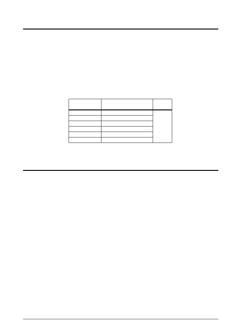
Table 11.2.1 Interrupt request and interrupt vectors
Interrupt vector
Interrupt request
Priority
(PCP and PCS)
102H
Clock timer interrupt
Low
104H
Stopwatch timer interrupt
↑
106H
Input (K00–K03) interrupt
108H
Input (K10–K13) interrupt
10AH
Serial interface interrupt
↓
10CH
Programmable timer interrupt
High
When multiple interrupts simultaneously occur, the high priority vector address is set to the program
counter.
11.3 Programming Notes
(1) The interrupt factor flag is set when the interrupt conditions are established, regardless of the setting
of the interrupt mask register. Note, however, that the input interrupt factor flags (IK0 and IK1) will
be eliminated.
(2) When an interrupt occurs, the interrupt flag will be reset by the hardware and it will become DI
status. After completion of the interrupt processing, set to the EI status through the software as
needed.
Moreover, the nesting level may be set to be programmable by setting to the EI state at the beginning
of the interrupt processing routine.
(3) The interrupt factor flags must always be reset before setting the EI status. When the interrupt mask
register has been set to "1", the same interrupt will occur again if the EI status is set unless of resetting
the interrupt factor flag.
(4) The interrupt factor flag will be reset by reading through the software. Because of this, when multiple
interrupt factor flags are to be assigned to the same address, perform the flag check after the contents
of the address has been stored in the RAM. Direct checking with the FAN instruction will cause all the
interrupt factor flag to be reset.
(5) Be sure that the interrupt factor flag reading is done with the interrupt in the DISABLE state (DI).
Reading the interrupt factor flag while in the ENABLE state (EI) may cause malfunction.
(6) Be sure that writing to the interrupt mask register is done with the interrupt in the DISABLE state
(DI). Writing to the interrupt mask register while in the ENABLE state (EI) may cause malfunction.
(7) When multiple interrupts simultaneously occur, the high priority vector address is set to the program
counter.
相關(guān)PDF資料 |
PDF描述 |
|---|---|
| S1C88104P0A0100 | 8-BIT, MROM, 8.2 MHz, MICROCONTROLLER, PBGA240 |
| S1C88317D0A0100 | MICROCONTROLLER, UUC170 |
| S1C88308D0A0100 | MICROCONTROLLER, UUC170 |
| S1C88308F0A0100 | MICROCONTROLLER, PQFP160 |
| S1C88348F | 8-BIT, MROM, 8.2 MHz, MICROCONTROLLER, PQFP16 |
相關(guān)代理商/技術(shù)參數(shù) |
參數(shù)描述 |
|---|---|
| S1C7309X | 制造商:SAMSUNG 制造商全稱:Samsung semiconductor 功能描述:B/W CCD PROCESSOR |
| S1C7309X01 | 制造商:SAMSUNG 制造商全稱:Samsung semiconductor 功能描述:B/W CCD PROCESSOR |
| S1C88349 | 制造商:EPSON 制造商全稱:EPSON 功能描述:8-bit Single Chip Microcomputer |
| S1C88649 | 制造商:EPSON 制造商全稱:EPSON 功能描述:8-bit Single Chip Microcomputer |
| S1C88650 | 制造商:EPSON 制造商全稱:EPSON 功能描述:8-bit Single Chip Microcomputer |
發(fā)布緊急采購,3分鐘左右您將得到回復(fù)。