- 您現(xiàn)在的位置:買賣IC網(wǎng) > PDF目錄2012 > MC92604ZT (Freescale Semiconductor)IC TXRX ETH DUAL GIG 196-MAPBGA PDF資料下載
參數(shù)資料
| 型號: | MC92604ZT |
| 廠商: | Freescale Semiconductor |
| 文件頁數(shù): | 95/122頁 |
| 文件大小: | 0K |
| 描述: | IC TXRX ETH DUAL GIG 196-MAPBGA |
| 標準包裝: | 630 |
| 類型: | 收發(fā)器 |
| 驅動器/接收器數(shù): | 2/2 |
| 規(guī)程: | 千兆位以太網(wǎng) |
| 電源電壓: | 4.5 V ~ 5.5 V |
| 安裝類型: | 表面貼裝 |
| 封裝/外殼: | 196-LBGA |
| 供應商設備封裝: | 196-MAPBGA(15x15) |
| 包裝: | 托盤 |
第1頁第2頁第3頁第4頁第5頁第6頁第7頁第8頁第9頁第10頁第11頁第12頁第13頁第14頁第15頁第16頁第17頁第18頁第19頁第20頁第21頁第22頁第23頁第24頁第25頁第26頁第27頁第28頁第29頁第30頁第31頁第32頁第33頁第34頁第35頁第36頁第37頁第38頁第39頁第40頁第41頁第42頁第43頁第44頁第45頁第46頁第47頁第48頁第49頁第50頁第51頁第52頁第53頁第54頁第55頁第56頁第57頁第58頁第59頁第60頁第61頁第62頁第63頁第64頁第65頁第66頁第67頁第68頁第69頁第70頁第71頁第72頁第73頁第74頁第75頁第76頁第77頁第78頁第79頁第80頁第81頁第82頁第83頁第84頁第85頁第86頁第87頁第88頁第89頁第90頁第91頁第92頁第93頁第94頁當前第95頁第96頁第97頁第98頁第99頁第100頁第101頁第102頁第103頁第104頁第105頁第106頁第107頁第108頁第109頁第110頁第111頁第112頁第113頁第114頁第115頁第116頁第117頁第118頁第119頁第120頁第121頁第122頁
System Design Considerations
MC92604 Dual Gigabit Ethernet Transceiver Reference Manual, Rev. 1
5-6
Freescale Semiconductor
5.7
Power Supply Requirements
The recommended board for the MC92604 has a minimum of two solid planes of 1-ounce copper. One
plane is to be used as a ground plane and the second plane is to be used for the 1.8-V supply. It is
recommended that the board has its own 1.8- and 3.3-V regulators with less than 50-mV ripple.
5.8
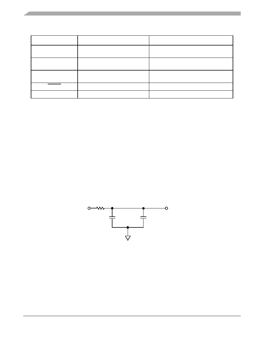
Phase-Locked Loop (PLL) Power Supply Filtering
An analog power supply is required. The PLLAVDD signal provides power for the analog portions of the
PLL. To ensure stability of the internal clock, the power supplied to the PLL is filtered using a circuit
similar to the one shown in Figure 5-1. For maximum effectiveness, the filter circuit is placed as close as
possible to the PLLAVDD ball to ensure that it filters out as much noise as possible. The ground connection
should be near the PLLAGND ball. The 0.01-
F capacitor is closest to the ball, followed by the 1-F
capacitor, and finally the 1-
resistor to VDD on the 1.8-V power plane. The capacitors are connected from
PLLAGND to the ground plane. Ceramic chip capacitors with the highest possible self-resonant frequency
should be used. All traces should be kept short, wide, and direct.
Figure 5-1. PLL Power Supply Filter Circuits
TST_0, TST_1
Test mode identifiers
Must be low and remain low during normal
operation. Device must be reset if changed.
LBOE
Loopback output enable
Enable/disable transmit links during testing
(LBOE = high). No recovery action necessary,
STNDBY
Puts PLL in standby mode
Receiver must re-establish byte and word
synchronization
RESET
System reset bar
Device is reset
ENABLE_RED
Enable redundant mode
Device must be reset
Table 5-3. Asynchronous Configuration and Control Signals (continued)
Signal Name
Description
Effect of Changed State
VDD
1
0.01 F
PLLAVDD
1.0 F
GND
相關PDF資料 |
PDF描述 |
|---|---|
| MCP2120T-I/SL | IC ENCODR/DECODR 2.5V IR 14-SOIC |
| MCP2122-E/P | IC ENCODER/DECODER IRDA 8-DIP |
| MCP2122T-E/SNG | IC ENCODER/DECODR INFRARED 8SOIC |
| MCP3901A0T-E/SS | IC ENERGY METER AFE 2CH 20-SSOP |
| MCP3903T-E/SS | IC AFE 24BIT 64KSPS 6CH 28SSOP |
相關代理商/技術參數(shù) |
參數(shù)描述 |
|---|---|
| MC92610 | 制造商:MOTOROLA 制造商全稱:Motorola, Inc 功能描述:Quad 3.125 Gbaud SERDES |
| MC92610VF | 制造商:MOTOROLA 制造商全稱:Motorola, Inc 功能描述:Quad 3.125 Gbaud SERDES |
| MC928G | 制造商:Rochester Electronics LLC 功能描述:- Bulk 制造商:Motorola Inc 功能描述: 制造商:MOTOROLA 功能描述: |
| MC929F | 制造商:Rochester Electronics LLC 功能描述:- Bulk 制造商:Motorola Inc 功能描述: |
| MC929G | 制造商:Rochester Electronics LLC 功能描述:- Bulk |
發(fā)布緊急采購,3分鐘左右您將得到回復。