- 您現(xiàn)在的位置:買賣IC網(wǎng) > PDF目錄2012 > MC92604ZT (Freescale Semiconductor)IC TXRX ETH DUAL GIG 196-MAPBGA PDF資料下載
參數(shù)資料
| 型號: | MC92604ZT |
| 廠商: | Freescale Semiconductor |
| 文件頁數(shù): | 60/122頁 |
| 文件大小: | 0K |
| 描述: | IC TXRX ETH DUAL GIG 196-MAPBGA |
| 標準包裝: | 630 |
| 類型: | 收發(fā)器 |
| 驅(qū)動器/接收器數(shù): | 2/2 |
| 規(guī)程: | 千兆位以太網(wǎng) |
| 電源電壓: | 4.5 V ~ 5.5 V |
| 安裝類型: | 表面貼裝 |
| 封裝/外殼: | 196-LBGA |
| 供應商設(shè)備封裝: | 196-MAPBGA(15x15) |
| 包裝: | 托盤 |
第1頁第2頁第3頁第4頁第5頁第6頁第7頁第8頁第9頁第10頁第11頁第12頁第13頁第14頁第15頁第16頁第17頁第18頁第19頁第20頁第21頁第22頁第23頁第24頁第25頁第26頁第27頁第28頁第29頁第30頁第31頁第32頁第33頁第34頁第35頁第36頁第37頁第38頁第39頁第40頁第41頁第42頁第43頁第44頁第45頁第46頁第47頁第48頁第49頁第50頁第51頁第52頁第53頁第54頁第55頁第56頁第57頁第58頁第59頁當前第60頁第61頁第62頁第63頁第64頁第65頁第66頁第67頁第68頁第69頁第70頁第71頁第72頁第73頁第74頁第75頁第76頁第77頁第78頁第79頁第80頁第81頁第82頁第83頁第84頁第85頁第86頁第87頁第88頁第89頁第90頁第91頁第92頁第93頁第94頁第95頁第96頁第97頁第98頁第99頁第100頁第101頁第102頁第103頁第104頁第105頁第106頁第107頁第108頁第109頁第110頁第111頁第112頁第113頁第114頁第115頁第116頁第117頁第118頁第119頁第120頁第121頁第122頁
Receiver
MC92604 Dual Gigabit Ethernet Transceiver Reference Manual, Rev. 1
3-8
Freescale Semiconductor
In the reduced interface operational modes, the receiver signals RECV_x_7 through RECV_x_4 are not
used and the 5th and 9th data bits are output on the RECV_x_DV signal. With the reduced interface, data
in the alignment FIFO is presented at the receiver interface as double data rate (DDR), on the rising and
falling edge of the appropriate receiver clock, RECV_x_RCLK.
The receiver status and error reporting is coded onto the RECV_x_ERR, RECV_x_DV,
RECV_x_COMMA, and RECV_x_K signals.
All of the digital outputs of the device are internally “source terminated” and therefore do not require
external device resistors on the pcb. This applies to all received data, status, and clock outputs on the
MC92604.
3.5
Data Alignment Configurations
The receiver supports two modes of byte alignment as defined by the BSYNC signal. Table 3-4 shows the
settings to activate each mode.
NOTE
Do not use non-aligned mode (BSYNC = low) in 8-bit modes. The
non-aligned mode is only valid if TBIE is high.
3.5.1
Non-Aligned Mode (BSYNC = Low)
In non-aligned mode no attempt is made to align the incoming data stream. The bits are simply
accumulated into 10-bit code groups and forwarded. This mode should be used only with backplane 10-
or 5-bit data mode (TBIE = high, COMPAT = low), and with word synchronization disabled
(WSYNC1 = low and WSYNC0 = low).
3.5.2
Byte-Aligned Mode (BSYNC = High)
The remaining 4 receiver operating modes, shown in Table 3-3 align the incoming serial data into 10-bit
code groups. At power up, the receiver starts an alignment procedure, searching for the 8-bit pattern
defined by the 8B/10B COMMA codes. Synchronization logic checks for the distinct sequence,
‘00111110xx’ and ‘11000001xx’ (ordered bit 0–7), characteristic of the three valid COMMA code group
patterns. The search is done on the 10-bit data in the receiver, and is, therefore, independent of the state of
TBIE or COMPAT. Alignment requires a minimum of four, error-free, received COMMA code groups to
ensure proper alignment and lock. Non-COMMA code groups may be interspersed with the COMMA
code groups. The disparity of the COMMA code groups is not important to alignment and can be positive,
negative, or any combination. The receiver begins to forward received code groups once locked on an
alignment.
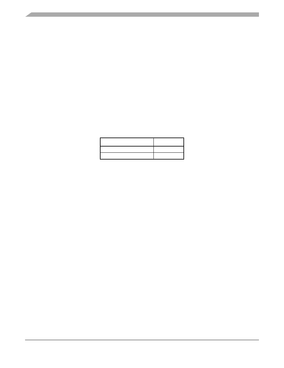
Table 3-4. Byte Synchronization Modes
Byte Alignment Mode
BSYNC
Byte Aligned
High
Non-Aligned
Low
相關(guān)PDF資料 |
PDF描述 |
|---|---|
| MCP2120T-I/SL | IC ENCODR/DECODR 2.5V IR 14-SOIC |
| MCP2122-E/P | IC ENCODER/DECODER IRDA 8-DIP |
| MCP2122T-E/SNG | IC ENCODER/DECODR INFRARED 8SOIC |
| MCP3901A0T-E/SS | IC ENERGY METER AFE 2CH 20-SSOP |
| MCP3903T-E/SS | IC AFE 24BIT 64KSPS 6CH 28SSOP |
相關(guān)代理商/技術(shù)參數(shù) |
參數(shù)描述 |
|---|---|
| MC92610 | 制造商:MOTOROLA 制造商全稱:Motorola, Inc 功能描述:Quad 3.125 Gbaud SERDES |
| MC92610VF | 制造商:MOTOROLA 制造商全稱:Motorola, Inc 功能描述:Quad 3.125 Gbaud SERDES |
| MC928G | 制造商:Rochester Electronics LLC 功能描述:- Bulk 制造商:Motorola Inc 功能描述: 制造商:MOTOROLA 功能描述: |
| MC929F | 制造商:Rochester Electronics LLC 功能描述:- Bulk 制造商:Motorola Inc 功能描述: |
| MC929G | 制造商:Rochester Electronics LLC 功能描述:- Bulk |
發(fā)布緊急采購,3分鐘左右您將得到回復。