- 您現(xiàn)在的位置:買賣IC網(wǎng) > PDF目錄382382 > PCF5083 (NXP Semiconductors N.V.) STEEL COVER PDF資料下載
參數(shù)資料
| 型號(hào): | PCF5083 |
| 廠商: | NXP Semiconductors N.V. |
| 英文描述: | STEEL COVER |
| 中文描述: | GSM信號(hào)處理IC |
| 文件頁(yè)數(shù): | 30/136頁(yè) |
| 文件大小: | 602K |
| 代理商: | PCF5083 |
第1頁(yè)第2頁(yè)第3頁(yè)第4頁(yè)第5頁(yè)第6頁(yè)第7頁(yè)第8頁(yè)第9頁(yè)第10頁(yè)第11頁(yè)第12頁(yè)第13頁(yè)第14頁(yè)第15頁(yè)第16頁(yè)第17頁(yè)第18頁(yè)第19頁(yè)第20頁(yè)第21頁(yè)第22頁(yè)第23頁(yè)第24頁(yè)第25頁(yè)第26頁(yè)第27頁(yè)第28頁(yè)第29頁(yè)當(dāng)前第30頁(yè)第31頁(yè)第32頁(yè)第33頁(yè)第34頁(yè)第35頁(yè)第36頁(yè)第37頁(yè)第38頁(yè)第39頁(yè)第40頁(yè)第41頁(yè)第42頁(yè)第43頁(yè)第44頁(yè)第45頁(yè)第46頁(yè)第47頁(yè)第48頁(yè)第49頁(yè)第50頁(yè)第51頁(yè)第52頁(yè)第53頁(yè)第54頁(yè)第55頁(yè)第56頁(yè)第57頁(yè)第58頁(yè)第59頁(yè)第60頁(yè)第61頁(yè)第62頁(yè)第63頁(yè)第64頁(yè)第65頁(yè)第66頁(yè)第67頁(yè)第68頁(yè)第69頁(yè)第70頁(yè)第71頁(yè)第72頁(yè)第73頁(yè)第74頁(yè)第75頁(yè)第76頁(yè)第77頁(yè)第78頁(yè)第79頁(yè)第80頁(yè)第81頁(yè)第82頁(yè)第83頁(yè)第84頁(yè)第85頁(yè)第86頁(yè)第87頁(yè)第88頁(yè)第89頁(yè)第90頁(yè)第91頁(yè)第92頁(yè)第93頁(yè)第94頁(yè)第95頁(yè)第96頁(yè)第97頁(yè)第98頁(yè)第99頁(yè)第100頁(yè)第101頁(yè)第102頁(yè)第103頁(yè)第104頁(yè)第105頁(yè)第106頁(yè)第107頁(yè)第108頁(yè)第109頁(yè)第110頁(yè)第111頁(yè)第112頁(yè)第113頁(yè)第114頁(yè)第115頁(yè)第116頁(yè)第117頁(yè)第118頁(yè)第119頁(yè)第120頁(yè)第121頁(yè)第122頁(yè)第123頁(yè)第124頁(yè)第125頁(yè)第126頁(yè)第127頁(yè)第128頁(yè)第129頁(yè)第130頁(yè)第131頁(yè)第132頁(yè)第133頁(yè)第134頁(yè)第135頁(yè)第136頁(yè)

1996 Oct 29
30
Philips Semiconductors
Objective specification
GSM signal processing IC
PCF5083
A power-down line is only deactivated during Sleep mode
if the corresponding activation register is programmed with
a higher value than register SLEEPCNT_REG. Otherwise
the power-down line stays active during Sleep mode. The
output polarity of the power-down lines can be changed by
setting their corresponding bit in register POL_REG to a
logic 1. The signals can be clamped to a level depending
on their flag in POL_REG by setting the corresponding bit
in register MASK_REG to a logic 0.
Because the 13 MHz clock is also internally disabled
during Sleep mode, the PCF5083 cannot be accessed
with the host port.
During Sleep mode, burst timing and frame interrupt
generation is stopped and the registers MODE0_REG and
MODE1_REG are cleared.
8.3.3.1
Transceiver control lines
The timing generator signals RXON, TXON, BEN, PDRX1,
PDRX2, PDTX1, NPDTX1, NPDTX2, PDBIAS, NPDBIAS,
PDSYN, TXKEY1, TXKEY2 and the RF device control bus
signals RFCLK, RFDO, RFEN1 to RFEN4, RFE and the
Voice Port signals ASF, ACLK and ADO are 3-stated as
long as the signal GPON1 is inactive during Sleep mode.
The signals are driven into their high-impedance state
independently of the actual polarity to which GPON1 is
programmed, unless MASK_REG[GPON1] = 0. In this
case the outputs are driven during Sleep mode.
8.3.3.2
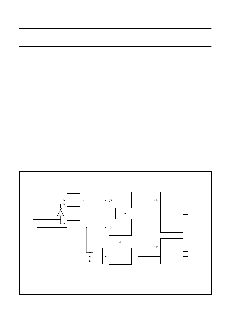
The Sleep Quarterbit Counter
In Sleep mode, the 13 MHz reference oscillator is switched
off to reduce the power consumption. The TDMA timing is
maintained using the sleep quarterbit counter (SQBC),
which is driven from the sleep clock (SLCLK). The sleep
clock is derived from the 32.768 kHz real time clock. Upon
entering Sleep mode, the contents of the quarterbit
counter are copied to the sleep quarterbit counter. After
the end of a Sleep mode period, the sleep quarterbit
counter is copied back to the quarterbit counter and normal
timing is performed again.
To maintain the correct timing over hundreds of TDMA
frames, the sleep quarterbit counter is incremented with
the value SQBC_INC equal to the clock ratio between the
quarterbit clock and the sleep clock. This value must be
very accurate and can be derived using the calibration
method described in Section 8.3.3.3.
Fig.10 Quarterbit counters for normal and Sleep mode.
handbook, full pagewidth
MGE289
QBCCTRL_REG[SLEEP]
QBCCTRL_REG[CAL]
13 MHz
1.08325 MHz
32768 Hz
SLCLK
8192 Hz
EN
÷
4
÷
12
QBC
(0 to 4999)
TIMING
GENERATOR
NORMAL
MODE
SQBC
RXON
Enter normal mode:
Copy SQBC to QBC
reduced
sleep
mode
Enter sleep mode:
Copy QBC to SQBC
SQBC_INC
(0 to 255)
typ. 123
1083
8.192
EN
TXON
BEN
PDRX1,2
(N)PDTX1,2
SYNON
(N)PDBIAS
TXKEY1,2
TIMING
GENERATOR
SLEEP
MODE
GPON1
GPON2
DSPON
REFON
NREFON
+
相關(guān)PDF資料 |
PDF描述 |
|---|---|
| PCF84C12A | 8-BIT MICROCONTROLLER |
| PCF84C12AP | 8-BIT MICROCONTROLLER |
| PCF84C12AT | 8-BIT MICROCONTROLLER |
| PCF84C21A | Telecom microcontrollers |
| PCF84C41A | Telecom microcontrollers |
相關(guān)代理商/技術(shù)參數(shù) |
參數(shù)描述 |
|---|---|
| PCF5083H/001/F2 | 制造商:PHILIPS 制造商全稱:NXP Semiconductors 功能描述:GSM signal processing IC |
| PCF5083H/5V2/F3 | 制造商:PHILIPS 制造商全稱:NXP Semiconductors 功能描述:GSM signal processing IC |
| PCF5083H/F2 | 制造商:PHILIPS 制造商全稱:NXP Semiconductors 功能描述:GSM signal processing IC |
| PCF51AC128ACFUE | 功能描述:32位微控制器 - MCU 32 Bit 128K FLASH 32K RAM CAN EN RoHS:否 制造商:Texas Instruments 核心:C28x 處理器系列:TMS320F28x 數(shù)據(jù)總線寬度:32 bit 最大時(shí)鐘頻率:90 MHz 程序存儲(chǔ)器大小:64 KB 數(shù)據(jù) RAM 大小:26 KB 片上 ADC:Yes 工作電源電壓:2.97 V to 3.63 V 工作溫度范圍:- 40 C to + 105 C 封裝 / 箱體:LQFP-80 安裝風(fēng)格:SMD/SMT |
| PCF51AC128ACLKE | 功能描述:32位微控制器 - MCU 32 Bit 128K FLASH 32K RAM CAN EN RoHS:否 制造商:Texas Instruments 核心:C28x 處理器系列:TMS320F28x 數(shù)據(jù)總線寬度:32 bit 最大時(shí)鐘頻率:90 MHz 程序存儲(chǔ)器大小:64 KB 數(shù)據(jù) RAM 大小:26 KB 片上 ADC:Yes 工作電源電壓:2.97 V to 3.63 V 工作溫度范圍:- 40 C to + 105 C 封裝 / 箱體:LQFP-80 安裝風(fēng)格:SMD/SMT |
發(fā)布緊急采購(gòu),3分鐘左右您將得到回復(fù)。