- 您現(xiàn)在的位置:買(mǎi)賣(mài)IC網(wǎng) > PDF目錄382686 > TSB12LV01APZ (Texas Instruments, Inc.) High-Speed Serial-Bus Link-Layer Controller PDF資料下載
參數(shù)資料
| 型號(hào): | TSB12LV01APZ |
| 廠(chǎng)商: | Texas Instruments, Inc. |
| 英文描述: | High-Speed Serial-Bus Link-Layer Controller |
| 中文描述: | 高速串行總線(xiàn)鏈路層控制器 |
| 文件頁(yè)數(shù): | 49/71頁(yè) |
| 文件大?。?/td> | 267K |
| 代理商: | TSB12LV01APZ |
第1頁(yè)第2頁(yè)第3頁(yè)第4頁(yè)第5頁(yè)第6頁(yè)第7頁(yè)第8頁(yè)第9頁(yè)第10頁(yè)第11頁(yè)第12頁(yè)第13頁(yè)第14頁(yè)第15頁(yè)第16頁(yè)第17頁(yè)第18頁(yè)第19頁(yè)第20頁(yè)第21頁(yè)第22頁(yè)第23頁(yè)第24頁(yè)第25頁(yè)第26頁(yè)第27頁(yè)第28頁(yè)第29頁(yè)第30頁(yè)第31頁(yè)第32頁(yè)第33頁(yè)第34頁(yè)第35頁(yè)第36頁(yè)第37頁(yè)第38頁(yè)第39頁(yè)第40頁(yè)第41頁(yè)第42頁(yè)第43頁(yè)第44頁(yè)第45頁(yè)第46頁(yè)第47頁(yè)第48頁(yè)當(dāng)前第49頁(yè)第50頁(yè)第51頁(yè)第52頁(yè)第53頁(yè)第54頁(yè)第55頁(yè)第56頁(yè)第57頁(yè)第58頁(yè)第59頁(yè)第60頁(yè)第61頁(yè)第62頁(yè)第63頁(yè)第64頁(yè)第65頁(yè)第66頁(yè)第67頁(yè)第68頁(yè)第69頁(yè)第70頁(yè)第71頁(yè)
5–1
5 Electrical Characteristics
5.1
Absolute Maximum Ratings Over Free-Air Temperature Range (Unless
Otherwise Noted)
Supply voltage range, V
CC
Supply voltage range, V
CC
5V
Input voltage range, V
I
(standard TTL/LVCMOS)
Input voltage range, V
I
(5-V standard TTL/LVCMOS)
Output voltage range, (standard TTL/LVCMOS) V
O
Output voltage range, (5-V standard TTL/LVCMOS) V
O
Input clamp current, I
IK
(TTL/LVCMOS) (V
I
< 0 or V
I
> V
CC
) (see Note 1)
Output clamp current, I
OK
(TTL/LVCMOS) (V
O
< 0 or V
O
> V
CC
) (see Note 2)
Continuous total power dissipation
. . . . . . . . . . . . . . . . .
Operating free-air temperature range, T
A
(TSB12LV01A)
–0.5 V to 3.6 V
–0.5 V to 5.5 V
–0.5 V to V
CC
+ 0.5 V
–0.5 V to V
CC
+ 0.5 V
–0.5 V to V
CC
+ 0.5 V
–0.5 V to V
CC
+ 0.5 V
. . . . . . . . . . . .
. . . . . . . .
. . . . . . . . . . . . . . . . . . . . . . . . . . . . . . . . . . . . . . . . . .
. . . . . . . . . . . . . . . . . . . . . . . . . . . . . . . . . . . . . . . .
. . . . . . . . . . . . . . . . . . .
. . . . . . . . . . . . . . . .
. . . . . . . . . . . . . . . . .
. . . . . . . . . . . . . .
±
20 mA
±
20 mA
See Maximum Dissipation Rating Table
. . . . . . . . . . . . . . . . . . . . .
. . . . . . . . . . . . . . . . . .
0
°
C to 70
°
C
–40
°
C to 85
°
C
–65
°
C to 150
°
C
(TSB12LV01AI)
. . . . . . . . . . . . . . . . . . . . . . . . . . . . . . . . . . . . .
Storage temperature range, T
stg
Stresses beyond those listed under “absolute maximum ratings” may cause permanent damage to the device. These
are stress ratings only, and functional operation of the device at these or any other conditions beyond those indicated
under “recommended operating conditions” is not implied. Exposure to absolute-maximum-rated conditions for
extended periods may affect device reliability.
NOTES:
1. This applies to external input and bidirectional buffers. For 5-V tolerant terminals, use VI > VCC5V.
2. This applies to external output and bidirectional buffers. For 5-V tolerant terminals, use VO > VCC5V.
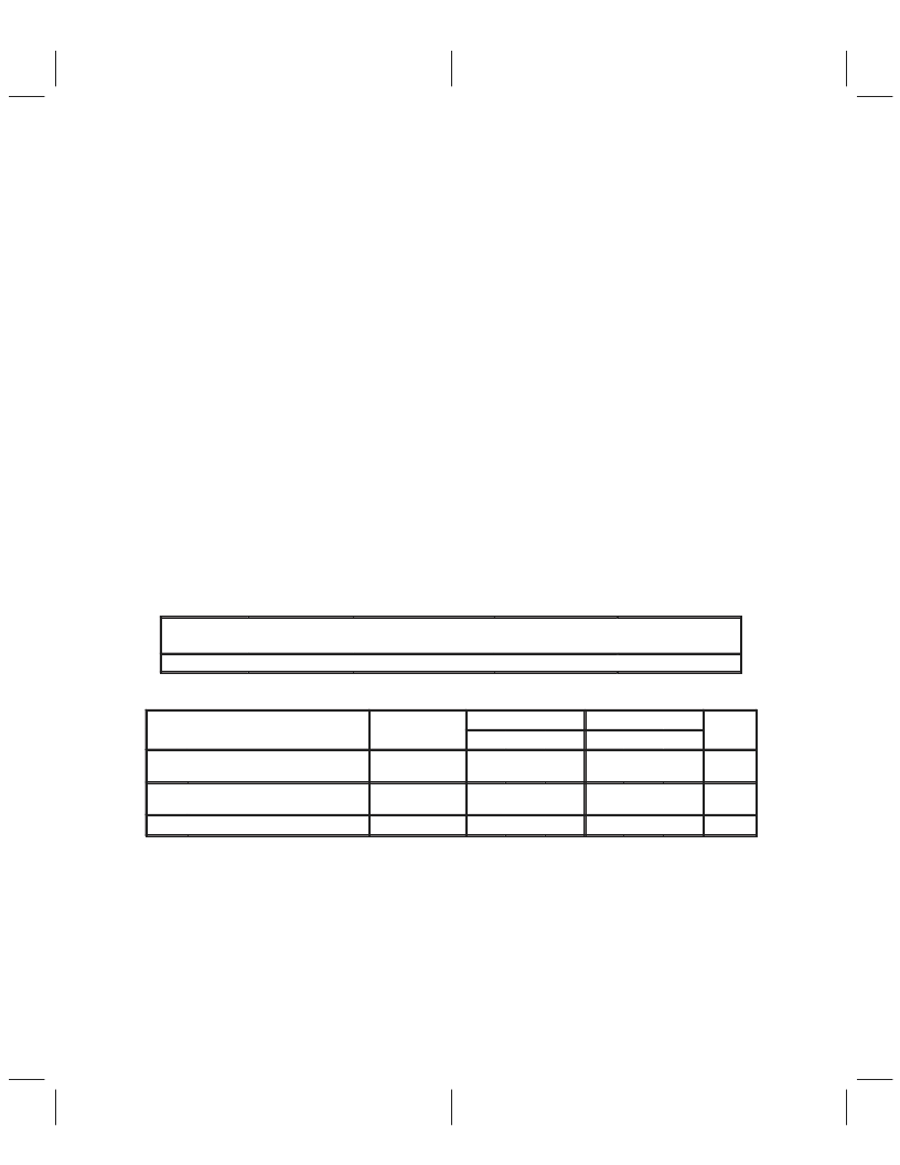
MAXIMUM DISSIPATION RATING TABLE
PACKAGE
TA
≤
25
°
C
POWER RATING
DERATING FACTOR
ABOVE TA = 25
°
C
16.9 mW/
°
C
TA = 70
°
C
POWER RATING
TA = 85
°
C
POWER RATING
PZ
1500 mW
737 mW
486 mW
PACKAGE THERMAL CHARACTERISTICS
PARAMETER
TEST
PZ PACKAGE
WN PACKAGE
UNIT
CONDITIONS
MIN
NOM
MAX
MIN
NOM
MAX
R
θ
JA
Junction-to-ambient thermal
impedance
Board mounted,
No air flow
59
52
°
C/W
R
θ
JC
Junction-to-case thermal
impedance
13
8
°
C/W
TJ
Thermal characteristics very depending on die and leadframe pad size as well as mold compound. These values
preresent typical die and pad sizes for the respective packages. The R value decreases as the die or pad sizes
increases. Thermal values represent PWB bands with minimal amounts of metal.
Junction temperature
115
175
°
C
相關(guān)PDF資料 |
PDF描述 |
|---|---|
| TSB3055 | IC APEX 20KE FPGA 300K 240-PQFP |
| TSB41AB3 | IC APEX 20KE FPGA 400K 672-FBGA |
| TSB41BA3-EP | IC APEX 20KE FPGA 400K 672-FBGA |
| TSB41LV03PFP | IC APEX 20KE FPGA 600K 652-BGA |
| TSB41AB2I | IEEE 1394a-2000 TWO-PORT CABLE TRANSCEVER/ARBITER |
相關(guān)代理商/技術(shù)參數(shù) |
參數(shù)描述 |
|---|---|
| TSB12LV01B | 制造商:TI 制造商全稱(chēng):Texas Instruments 功能描述:IEEE 1394-1995 HIGH SPEED SERIAL BUS LINK LAYER CONTROLLER |
| TSB12LV01B-EP | 制造商:未知廠(chǎng)家 制造商全稱(chēng):未知廠(chǎng)家 功能描述:Military Enhanced Plastic High Performance 1394 3.3V Link Layer for Telecom. Embedded & Indust. App. |
| TSB12LV01BIPZT | 功能描述:1394 接口集成電路 High Perf 1394 3.3V Link Layer RoHS:否 制造商:Texas Instruments 類(lèi)型:Link Layer Controller 工作電源電壓: 封裝 / 箱體:LQFP 封裝:Tray |
| TSB12LV01BIPZTEP | 功能描述:1394 接口集成電路 Mil Enh Hi Perf 1394 3.3V Link Layer RoHS:否 制造商:Texas Instruments 類(lèi)型:Link Layer Controller 工作電源電壓: 封裝 / 箱體:LQFP 封裝:Tray |
| TSB12LV01BPZ | 制造商:未知廠(chǎng)家 制造商全稱(chēng):未知廠(chǎng)家 功能描述:BUS CONTROLLER |
發(fā)布緊急采購(gòu),3分鐘左右您將得到回復(fù)。