- 您現(xiàn)在的位置:買賣IC網(wǎng) > PDF目錄382686 > TSB12LV01APZ (Texas Instruments, Inc.) High-Speed Serial-Bus Link-Layer Controller PDF資料下載
參數(shù)資料
| 型號: | TSB12LV01APZ |
| 廠商: | Texas Instruments, Inc. |
| 英文描述: | High-Speed Serial-Bus Link-Layer Controller |
| 中文描述: | 高速串行總線鏈路層控制器 |
| 文件頁數(shù): | 23/71頁 |
| 文件大小: | 267K |
| 代理商: | TSB12LV01APZ |
第1頁第2頁第3頁第4頁第5頁第6頁第7頁第8頁第9頁第10頁第11頁第12頁第13頁第14頁第15頁第16頁第17頁第18頁第19頁第20頁第21頁第22頁當前第23頁第24頁第25頁第26頁第27頁第28頁第29頁第30頁第31頁第32頁第33頁第34頁第35頁第36頁第37頁第38頁第39頁第40頁第41頁第42頁第43頁第44頁第45頁第46頁第47頁第48頁第49頁第50頁第51頁第52頁第53頁第54頁第55頁第56頁第57頁第58頁第59頁第60頁第61頁第62頁第63頁第64頁第65頁第66頁第67頁第68頁第69頁第70頁第71頁
3–5
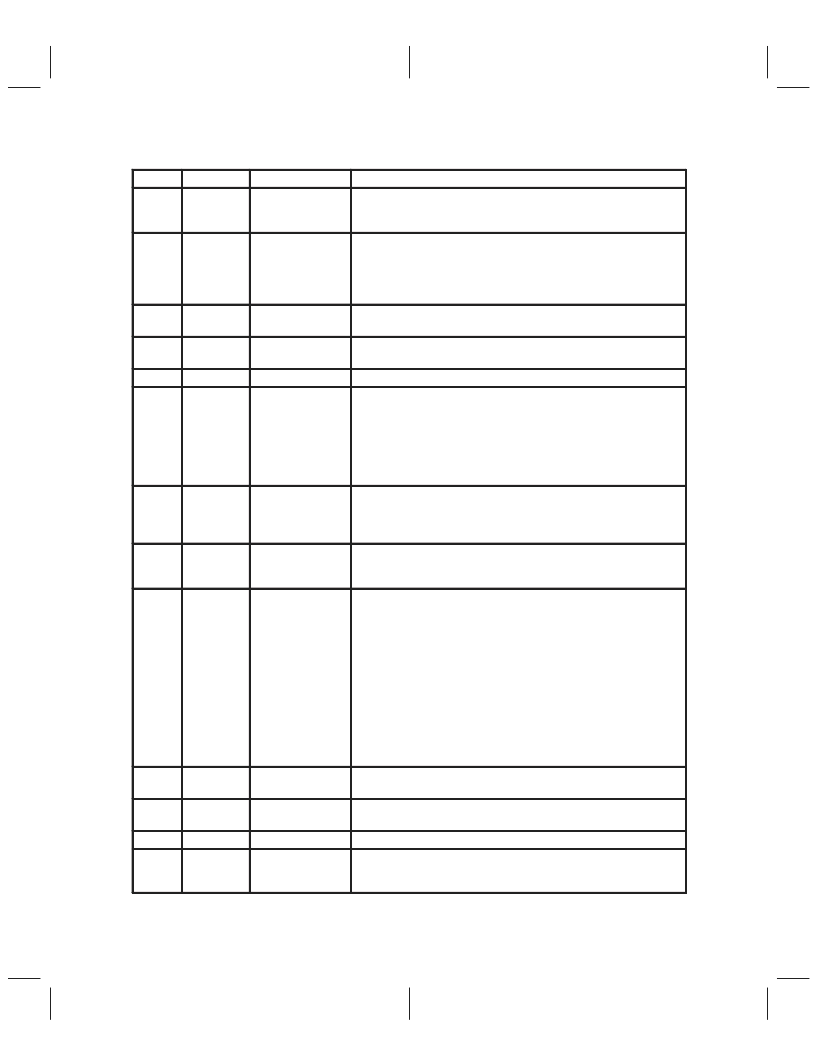
Table 3–3. Control-Register Field Descriptions (Continued)
BITS
8
ACRONYM
FUNCTION NAME
DESCRIPTION
RxIEn
Receive
isochronous
enable
When RxIEn is cleared, the receiver does not receive isochronous
packets.
9
AckCEn
Ack complete
enable
When AckCEn is set, the 12LV01A sends the Ack_complete code to the
transmit node for receiving a non-broadcast write request packet if
GRF is not full and there is no error in the packet. When AckCEn is
cleared, TSB12LV01A sends an Ack_pending code for the above
condition.
10
RstTx
Reset transmitter
When RstTx is set, the entire transmitter resets synchronously. This bit
clears itself.
11
RstRx
Reset receiver
When RstRx is set, the entire receiver resets synchronously. This bit
clears itself.
12–19
Reserved
Reserved
Reserved
20
CyMas
Cycle master
When CyMas is set and the TSB12LV01A is attached to the root phy,
the cyclemaster function is enabled. When the cycle_count field of the
cycle timer register increments, the transmitter sends a cycle-start
packet. This bit is not cleared upon bus reset. When another node is
selected as root during a bus reset, the transaction layer in the now
nonroot TSB12LV01A node must clear this bit and the transaction layer
in the TSB12LV01A node selected as root must set this bit.
21
CySrc
Cycle source
When CySrc is set, the cycle_count field increments and the
cycle_offset field resets for each positive transition of CYCLEIN. When
CySrc is cleared, the cycle_count field increments when the
cycle_offset field rolls over.
22
CyTEn
Cycle-timer enable
When CyTEn is set, the cycle_offset field increments. This bit must be
set to transmit cycle start packets for cycle master node. This bit
must
be set to receive or transmit isochronous packets.
23
TrgEn
Trigger size func-
tion enable
If TrgEn is set, the receiver partitions the received packet into trigger
size blocks. Trigger size is defined in FIFO Control register. For exam-
ple: if trigger size=8 and total received packet size (excluding header
CRC and data CRC)=20 quadlets. The receiver creates 3 blocks of
data in GRF. Each block starts with a packet token quadlet to indicate
how many quadlets follow this packet token. The first and the second
block have 9 quadlets (including the packet token quadlet). The third
block has 5 quadlets(including a packet token quadlet). Each block trig-
gers one RxDta interrupt. The purpose of the trigger size function is to
allow the receiver to receive a packet larger than GRF size and host bus
can read the received data when each block is available without waiting
till the whole packet is loaded into GRF, so the host bus latency is re-
duced.
24
IRP1En
IR port 1 enable
When IRP1En is set, the receiver accepts isochronous packets when
the channel number matches the value in the IR Port1 field.
25
IRP2En
IR port 2 enable
When IRP2En is set, the receiver accepts isochronous packets when
the channel number matches the value in the IR Port2 field.
26–30
31
Reserved
Reserved
Reserved
FhBad
Flush bad packets
When the FhBad is set, the receiver flushes any received bad packets
(including a partial packet due to GRF full)and it does not generate a
RxDta interrupt. When FhBad is set, it disables the TrgEn function.
This bit or bits are new to the TSB12LV01A and do not exist in the TSB12C01A.
相關(guān)PDF資料 |
PDF描述 |
|---|---|
| TSB3055 | IC APEX 20KE FPGA 300K 240-PQFP |
| TSB41AB3 | IC APEX 20KE FPGA 400K 672-FBGA |
| TSB41BA3-EP | IC APEX 20KE FPGA 400K 672-FBGA |
| TSB41LV03PFP | IC APEX 20KE FPGA 600K 652-BGA |
| TSB41AB2I | IEEE 1394a-2000 TWO-PORT CABLE TRANSCEVER/ARBITER |
相關(guān)代理商/技術(shù)參數(shù) |
參數(shù)描述 |
|---|---|
| TSB12LV01B | 制造商:TI 制造商全稱:Texas Instruments 功能描述:IEEE 1394-1995 HIGH SPEED SERIAL BUS LINK LAYER CONTROLLER |
| TSB12LV01B-EP | 制造商:未知廠家 制造商全稱:未知廠家 功能描述:Military Enhanced Plastic High Performance 1394 3.3V Link Layer for Telecom. Embedded & Indust. App. |
| TSB12LV01BIPZT | 功能描述:1394 接口集成電路 High Perf 1394 3.3V Link Layer RoHS:否 制造商:Texas Instruments 類型:Link Layer Controller 工作電源電壓: 封裝 / 箱體:LQFP 封裝:Tray |
| TSB12LV01BIPZTEP | 功能描述:1394 接口集成電路 Mil Enh Hi Perf 1394 3.3V Link Layer RoHS:否 制造商:Texas Instruments 類型:Link Layer Controller 工作電源電壓: 封裝 / 箱體:LQFP 封裝:Tray |
| TSB12LV01BPZ | 制造商:未知廠家 制造商全稱:未知廠家 功能描述:BUS CONTROLLER |
發(fā)布緊急采購,3分鐘左右您將得到回復(fù)。