- 您現(xiàn)在的位置:買賣IC網(wǎng) > PDF目錄370499 > HDMP-1024 Low Cost Gigabit Rate Receive Chip Set with TTL I/Os(帶TTL輸入/輸出的低價(jià)格千兆位速率接收芯片) PDF資料下載
參數(shù)資料
| 型號(hào): | HDMP-1024 |
| 英文描述: | Low Cost Gigabit Rate Receive Chip Set with TTL I/Os(帶TTL輸入/輸出的低價(jià)格千兆位速率接收芯片) |
| 中文描述: | 低成本千兆速率接收芯片組配備TTL的I / O(帶的TTL輸入/輸出的低價(jià)格千兆位速率接收芯片) |
| 文件頁(yè)數(shù): | 6/40頁(yè) |
| 文件大?。?/td> | 363K |
| 代理商: | HDMP-1024 |
第1頁(yè)第2頁(yè)第3頁(yè)第4頁(yè)第5頁(yè)當(dāng)前第6頁(yè)第7頁(yè)第8頁(yè)第9頁(yè)第10頁(yè)第11頁(yè)第12頁(yè)第13頁(yè)第14頁(yè)第15頁(yè)第16頁(yè)第17頁(yè)第18頁(yè)第19頁(yè)第20頁(yè)第21頁(yè)第22頁(yè)第23頁(yè)第24頁(yè)第25頁(yè)第26頁(yè)第27頁(yè)第28頁(yè)第29頁(yè)第30頁(yè)第31頁(yè)第32頁(yè)第33頁(yè)第34頁(yè)第35頁(yè)第36頁(yè)第37頁(yè)第38頁(yè)第39頁(yè)第40頁(yè)
6
of the frame rate is performed by
the transmitter. The clock
generator section performs the
clock multiplication to the
necessary serial clock rate.
By setting EHCLKSEL high, the
user may provide an external TTL
serial clock at STRBIN. This clock
replaces the internal VCO clock
and is intended for diagnostic
purposes only. This clock is used
directly by the high speed serial
circuitry to output the serial data
at speeds that are not within the
VCO range. This signal is not
characterized.
Control Logic and C-Field
Encoder
The Control Logic is responsible
for determining what information
is serially sent to the output. If
CAV* is low, it sends the data at
D0..D8 and D9..D17 as control
word information regardless of
the state of DAV*. If CAV* is high
and DAV* is low, it sends parallel
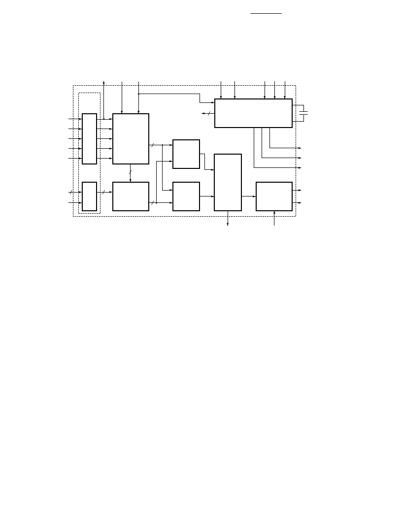
HDMP-1022 Tx Block
Diagram
The HDMP-1022 was designed to
accept 16 or 20 bit wide parallel
data (frames) and transmit it over
a high speed serial line. Many of
the link management functions are
integrated into the HDMP-1022,
thereby greatly minimizing the
design effort. The HDMP-1022
performs the following functions:
Parallel Word Input
High Speed Clock Multiplication
Frame Encoding
Parallel to Serial Multiplexing
PLL/Clock Generator
The Phase Locked Loop and Clock
Generator are responsible for
generating all internal clocks
needed by the transmitter to
perform its functions. These
clocks are based on a supplied
frame clock (STRBIN) and control
signals (M20SEL, MDFSEL,
EHCLKSEL, DIV1, DIV0). In
single frame mode (MDFSEL=0),
STRBIN is expected to be the
incoming frame clock. The PLL/
Clock Generator locks on to this
incoming rate and multiplies the
clock up to the needed high speed
serial clock. Based on M20SEL,
which determines whether the
incoming data frame is 16 or 20
bits wide, the PLL/Clock Gener-
ator multiplies the frame rate
clock by 20 or 24 respectively
(data bits + 4 control bits). DIV1/
DIV0 are set to inform the
transmitter of the frequency range
of the incoming data frames. The
internal frame rate clock is
accessible through STRBOUT Z"d
the high speed serial clock is
accessible through HCLK.
When MDFSEL is set high, the
transmitter is in Double Frame
Mode. Using this option, the user
may send a 32 or 40 bit wide data
frame in two segments while
supplying the original 32 or 40 bit
frame clock at STRBIN. Doubling
Figure 4. HDMP-1022 Transmitter Block Diagram.
ED
CONTROL
LOGIC
+
C-FIELD
ENCODER
FF
CAV*
DAV*
FLAG
D0-D19
RST*
D-FIELD
ENCODER
L
L
SIGN
FRAME
MUX
R
F
M
S
E
D
D
M
PLL / CLOCK
GENERATOR
A
OUTPUT
SELECT
CAP0
CAP1
0.1 μF
STRBOUT
HCLK
±
LOCKED
DOUT
±
LOUT
±
LOOPEN
INV
INTERNAL
CLOCKS
INPUT
LATCH
相關(guān)PDF資料 |
PDF描述 |
|---|---|
| HDMP-1032 | 1.4 GBd Transmitter Chip Set with CIMT Encoder/Decoder and Variable Data Rate(帶CIMT編碼器/譯碼器和變量數(shù)據(jù)速率的1.4 GBd 傳送器) |
| HDMP-1034 | 1.4 GBd Receiver Chip Set with CIMT Encoder/Decoder and Variable Data Rate(帶CIMT編碼器/譯碼器和變量數(shù)據(jù)速率的1.4 GBd 接收器) |
| HDMP-1512 | Fibre Channel Transmitter Chipset(光纖通道傳送芯片) |
| HDMP-1514 | Fibre Channel Receiver Chipset(光纖通道接收芯片) |
| HDMP-1526 | Transistor Diode Kit;Contents Of Kit:Transistor/Diode Kit |
相關(guān)代理商/技術(shù)參數(shù) |
參數(shù)描述 |
|---|---|
| HDMP-1032 | 制造商:AGILENT 制造商全稱:AGILENT 功能描述:1.4 GBd Transmitter/Receiver Chip Set with CIMT Encoder/Decoder and Variable Data Rate |
| HDMP-1032A | 制造商:未知廠家 制造商全稱:未知廠家 功能描述:1.4 GBd Transmitter Chip with CIMT Encoder/Decoder and Variable Data Rate |
| HDMP-1034 | 制造商:AGILENT 制造商全稱:AGILENT 功能描述:1.4 GBd Transmitter/Receiver Chip Set with CIMT Encoder/Decoder and Variable Data Rate |
| HDMP-1034A | 制造商:HP 制造商全稱:Agilent(Hewlett-Packard) 功能描述:Transmitter/Receiver Chip Set |
| HDMP-1512 | 制造商:AGILENT 制造商全稱:AGILENT 功能描述:Fibre Channel Transmitter and Receiver Chipset |
發(fā)布緊急采購(gòu),3分鐘左右您將得到回復(fù)。