- 您現(xiàn)在的位置:買賣IC網 > PDF目錄370499 > HDMP-1024 Low Cost Gigabit Rate Receive Chip Set with TTL I/Os(帶TTL輸入/輸出的低價格千兆位速率接收芯片) PDF資料下載
參數(shù)資料
| 型號: | HDMP-1024 |
| 英文描述: | Low Cost Gigabit Rate Receive Chip Set with TTL I/Os(帶TTL輸入/輸出的低價格千兆位速率接收芯片) |
| 中文描述: | 低成本千兆速率接收芯片組配備TTL的I / O(帶的TTL輸入/輸出的低價格千兆位速率接收芯片) |
| 文件頁數(shù): | 32/40頁 |
| 文件大?。?/td> | 363K |
| 代理商: | HDMP-1024 |
第1頁第2頁第3頁第4頁第5頁第6頁第7頁第8頁第9頁第10頁第11頁第12頁第13頁第14頁第15頁第16頁第17頁第18頁第19頁第20頁第21頁第22頁第23頁第24頁第25頁第26頁第27頁第28頁第29頁第30頁第31頁當前第32頁第33頁第34頁第35頁第36頁第37頁第38頁第39頁第40頁
32
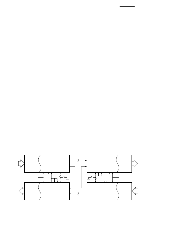
Figure 16. Full Duplex Configuration.
Appendix II: Link
Configuration Examples
This section shows some
application examples using the
HDMP-1022/1024 chipset. Refer
to
I/O Definition
for detailed
circuit-level interconnections.
This guide is intended to aid the
user in designing G-LINK into a
system. It provides the necessary
details of getting the system up,
without the detailed description of
the inner circuitry of the chip set.
The first section is a description
of the various configurations for
duplex and simplex operation.
The second section describes the
interface to both single frame and
double frame mode. Following
that is a section on the integrating
capacitor and power supply
bypassing recommendations.
Next is a guide to the various
types of electrical I/O connec-
tions. Also included is a list of the
various options and their
definitions.
Duplex/Simplex
Configurations
The following describes the
common setups for the link. In all
cases, the DIN and LIN are
differential high speed lines, and
unused leads should be terminated
with 50
AC coupled to ground.
Since the data stream has no DC
component, a coupling cap of
0.1
μ
F is recommended for the
DIN and LIN inputs.
Full Duplex
Figure 16 shows HDMP-1022/
1024 in a full duplex configura-
tion connecting two bidirectional
(parallel) buses. Each end of the
link has a Tx and Rx pair. The
receiver’s state machine outputs
(STAT0 and STAT1) are used to
control the status of the link.
Various options such as 16/20 bit
mode (M20SEL) and speed
selections (DIV0,DIV1) are
grouped together under the label
‘options.’ A power-on reset is
available to the user to reset the
link during startup.
When the Tx has acquired lock to
the incoming STRBIN at the
frame rate, the LOCKED pin is
activated, which enables the Rx.
At this state, both STAT0 and
STAT1 are low, forcing the Tx to
send FF0, which is a square wave
pattern used by the remote Rx to
acquire frame lock. When the
local Rx has acquired frame lock,
STAT1 is set high to first turn off
its own frequency detector
(FDIS), then self sets to active
mode (ACTIVE), and tells the
local Tx to send FF1 to signal the
remote Rx that the local pair is
ready. Likewise, when the remote
pair is ready, the local Rx will
receive FF1, causing STAT0 to go
high, which asserts the enable
data (ED) pin on the Tx. The ED
signal is retimed to signify to the
host that the Tx is ready to send
Tx DATA
INTERFACE
DOUT
R
L
E
F
OPTIONS
Rx DATA
INTERFACE
DIN
A
F
S
S
S
S
LIN
Rx
Tx
Rx DATA
INTERFACE
LIN
S
S
S
S
F
A
DIN
Tx DATA
INTERFACE
LOUT
F
E
L
R
DOUT
Tx
Rx
POWER-ON
RESET
LOUT
POWER-ON
RESET
OPTIONS
相關PDF資料 |
PDF描述 |
|---|---|
| HDMP-1032 | 1.4 GBd Transmitter Chip Set with CIMT Encoder/Decoder and Variable Data Rate(帶CIMT編碼器/譯碼器和變量數(shù)據(jù)速率的1.4 GBd 傳送器) |
| HDMP-1034 | 1.4 GBd Receiver Chip Set with CIMT Encoder/Decoder and Variable Data Rate(帶CIMT編碼器/譯碼器和變量數(shù)據(jù)速率的1.4 GBd 接收器) |
| HDMP-1512 | Fibre Channel Transmitter Chipset(光纖通道傳送芯片) |
| HDMP-1514 | Fibre Channel Receiver Chipset(光纖通道接收芯片) |
| HDMP-1526 | Transistor Diode Kit;Contents Of Kit:Transistor/Diode Kit |
相關代理商/技術參數(shù) |
參數(shù)描述 |
|---|---|
| HDMP-1032 | 制造商:AGILENT 制造商全稱:AGILENT 功能描述:1.4 GBd Transmitter/Receiver Chip Set with CIMT Encoder/Decoder and Variable Data Rate |
| HDMP-1032A | 制造商:未知廠家 制造商全稱:未知廠家 功能描述:1.4 GBd Transmitter Chip with CIMT Encoder/Decoder and Variable Data Rate |
| HDMP-1034 | 制造商:AGILENT 制造商全稱:AGILENT 功能描述:1.4 GBd Transmitter/Receiver Chip Set with CIMT Encoder/Decoder and Variable Data Rate |
| HDMP-1034A | 制造商:HP 制造商全稱:Agilent(Hewlett-Packard) 功能描述:Transmitter/Receiver Chip Set |
| HDMP-1512 | 制造商:AGILENT 制造商全稱:AGILENT 功能描述:Fibre Channel Transmitter and Receiver Chipset |
發(fā)布緊急采購,3分鐘左右您將得到回復。