- 您現(xiàn)在的位置:買賣IC網(wǎng) > PDF目錄98079 > SCD243110QCD (INTEL CORP) 4 CHANNEL(S), 134.4K bps, SERIAL COMM CONTROLLER, PQFP100 PDF資料下載
參數(shù)資料
| 型號(hào): | SCD243110QCD |
| 廠商: | INTEL CORP |
| 元件分類: | 微控制器/微處理器 |
| 英文描述: | 4 CHANNEL(S), 134.4K bps, SERIAL COMM CONTROLLER, PQFP100 |
| 封裝: | METRIC, QFP-100 |
| 文件頁(yè)數(shù): | 162/186頁(yè) |
| 文件大?。?/td> | 2204K |
| 代理商: | SCD243110QCD |
第1頁(yè)第2頁(yè)第3頁(yè)第4頁(yè)第5頁(yè)第6頁(yè)第7頁(yè)第8頁(yè)第9頁(yè)第10頁(yè)第11頁(yè)第12頁(yè)第13頁(yè)第14頁(yè)第15頁(yè)第16頁(yè)第17頁(yè)第18頁(yè)第19頁(yè)第20頁(yè)第21頁(yè)第22頁(yè)第23頁(yè)第24頁(yè)第25頁(yè)第26頁(yè)第27頁(yè)第28頁(yè)第29頁(yè)第30頁(yè)第31頁(yè)第32頁(yè)第33頁(yè)第34頁(yè)第35頁(yè)第36頁(yè)第37頁(yè)第38頁(yè)第39頁(yè)第40頁(yè)第41頁(yè)第42頁(yè)第43頁(yè)第44頁(yè)第45頁(yè)第46頁(yè)第47頁(yè)第48頁(yè)第49頁(yè)第50頁(yè)第51頁(yè)第52頁(yè)第53頁(yè)第54頁(yè)第55頁(yè)第56頁(yè)第57頁(yè)第58頁(yè)第59頁(yè)第60頁(yè)第61頁(yè)第62頁(yè)第63頁(yè)第64頁(yè)第65頁(yè)第66頁(yè)第67頁(yè)第68頁(yè)第69頁(yè)第70頁(yè)第71頁(yè)第72頁(yè)第73頁(yè)第74頁(yè)第75頁(yè)第76頁(yè)第77頁(yè)第78頁(yè)第79頁(yè)第80頁(yè)第81頁(yè)第82頁(yè)第83頁(yè)第84頁(yè)第85頁(yè)第86頁(yè)第87頁(yè)第88頁(yè)第89頁(yè)第90頁(yè)第91頁(yè)第92頁(yè)第93頁(yè)第94頁(yè)第95頁(yè)第96頁(yè)第97頁(yè)第98頁(yè)第99頁(yè)第100頁(yè)第101頁(yè)第102頁(yè)第103頁(yè)第104頁(yè)第105頁(yè)第106頁(yè)第107頁(yè)第108頁(yè)第109頁(yè)第110頁(yè)第111頁(yè)第112頁(yè)第113頁(yè)第114頁(yè)第115頁(yè)第116頁(yè)第117頁(yè)第118頁(yè)第119頁(yè)第120頁(yè)第121頁(yè)第122頁(yè)第123頁(yè)第124頁(yè)第125頁(yè)第126頁(yè)第127頁(yè)第128頁(yè)第129頁(yè)第130頁(yè)第131頁(yè)第132頁(yè)第133頁(yè)第134頁(yè)第135頁(yè)第136頁(yè)第137頁(yè)第138頁(yè)第139頁(yè)第140頁(yè)第141頁(yè)第142頁(yè)第143頁(yè)第144頁(yè)第145頁(yè)第146頁(yè)第147頁(yè)第148頁(yè)第149頁(yè)第150頁(yè)第151頁(yè)第152頁(yè)第153頁(yè)第154頁(yè)第155頁(yè)第156頁(yè)第157頁(yè)第158頁(yè)第159頁(yè)第160頁(yè)第161頁(yè)當(dāng)前第162頁(yè)第163頁(yè)第164頁(yè)第165頁(yè)第166頁(yè)第167頁(yè)第168頁(yè)第169頁(yè)第170頁(yè)第171頁(yè)第172頁(yè)第173頁(yè)第174頁(yè)第175頁(yè)第176頁(yè)第177頁(yè)第178頁(yè)第179頁(yè)第180頁(yè)第181頁(yè)第182頁(yè)第183頁(yè)第184頁(yè)第185頁(yè)第186頁(yè)
Advanced Multi-Protocol Communications Controller — CD2431
Datasheet
77
flow control characters are not transmitted. For example, it does not transmit an XON simply
because the number of characters is below the threshold; it only does so if it had previously sent an
XOFF due to the threshold being exceeded. For this reason, the user should not use the Send
Special Character command in the STCR (Special Transmit Command register) to send XON/
XOFF characters because the CD2431 does not keep track of flow control characters that it did not
send automatically. The result could cause confusion on the other end of the connection due to
conflicting flow control commands.
Automatic in-band flow control is functional only in standard Async and Async-HDLC/PPP
modes; SLIP and MNP 4 expressly forbid in-band flow control. See the COR5 description
(page 101) for programming details.
6.5.2
Out-of-Band Flow Control
Receive out-of-band flow control is enabled when the CtsAE bit (COR2[1]) is set to ‘1’. In this
mode, character transmission begins only after the CTS* pin is active (low). In asynchronous
transmission if CTS* goes inactive (high) after transmission starts, the channel stops transmission
after the current character in the Transmit Shift register, and the current characters in the Transmit
Holding register are transmitted. In Synchronous modes if CTS* goes inactive, the channel stops
transmission after the current frame. In either case, transmission restarts after CTS* goes active.
The CD2431 can automatically flow control the remote device by the DTR* pin. This mode is
selected by setting a non-zero DTR* threshold in COR5; when the thresholds in COR4 and COR5
are exceeded, the CD2431 sets the DTR* pin high. When the data in the FIFO falls below the
DTR* threshold, the DTR* pin is automatically driven low.
Each channel of the CD2431 has four pins that can be used either as a modem control or general-
purpose input/output pins. The modem signal names assigned to these four pins were selected to
provide an easy reference for system designers. In fact, they are all simply general-purpose inputs
and outputs (if automatic out-of-band flow-control is not used) that can be individually controlled
by the Modem Signal Value register(s). Since the pins are general-purpose, system designers can
choose to connect the pins in any way that is appropriate for the application.
However, when the system software design employs automatic out-of-band flow control with the
pins, the signal naming convention no longer holds true in some cases, depending on whether the
device is used as DCE or DTE. In this case, it is best to think of the pins in terms of their actual
uses within the CD2431 and connect them accordingly, without regard to their names. The RTS*
and CTS* pins are associated with transmitter, and the DTR* and DSR* pins are associated with
the receiver. The following table shows the recommended signal hook-up if automatic out-of-band
flow control is desired.
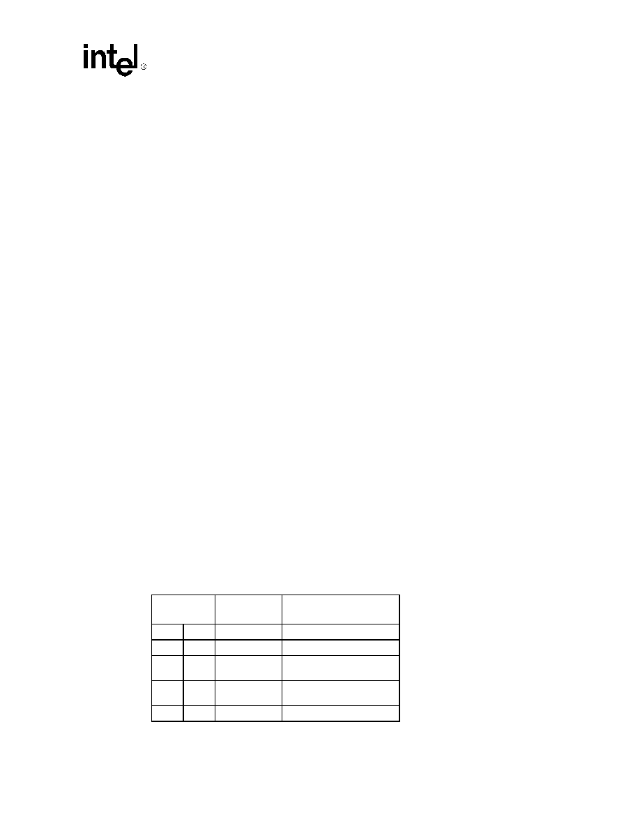
Table 11. Recommended Signal Connection
Mode
CD2431 Pin
Name
Out-of-Band
Flow Control
DCE
DTE
CTS
DTR
Signal remote to transmit
RTS
Not implemented in this
direction
RTS
Request remote permission
to transmit
CTS
Enable transmitter
相關(guān)PDF資料 |
PDF描述 |
|---|---|
| SCG2500AI-019.44M | 51.84 MHz, OTHER CLOCK GENERATOR, DSO14 |
| SCG4525 | 4000/14000/40000 SERIES, PLL BASED CLOCK DRIVER, 1 TRUE OUTPUT(S), 1 INVERTED OUTPUT(S), DSO18 |
| SCN2641CC1A28 | 1 CHANNEL(S), 1M bps, SERIAL COMM CONTROLLER, PQCC28 |
| SCN2681TC1A44A | 2 CHANNEL(S), 1M bps, SERIAL COMM CONTROLLER, PQCC44 |
| SCN68562C2N48 | 2 CHANNEL(S), 4M bps, MULTI PROTOCOL CONTROLLER, PDIP48 |
相關(guān)代理商/技術(shù)參數(shù) |
參數(shù)描述 |
|---|---|
| SCD248110QCD | 功能描述:IC 4CH WAN COMMUN CTRL 100QFP RoHS:否 類別:集成電路 (IC) >> 接口 - 控制器 系列:- 標(biāo)準(zhǔn)包裝:4,900 系列:- 控制器類型:USB 2.0 控制器 接口:串行 電源電壓:3 V ~ 3.6 V 電流 - 電源:135mA 工作溫度:0°C ~ 70°C 安裝類型:表面貼裝 封裝/外殼:36-VFQFN 裸露焊盤 供應(yīng)商設(shè)備封裝:36-QFN(6x6) 包裝:* 其它名稱:Q6396337A |
| SCD24H | 制造商:ZOWIE 制造商全稱:Zowie Technology Corporation 功能描述:Schottky Barrier Diode |
| SCD24L | 制造商:ZOWIE 制造商全稱:Zowie Technology Corporation 功能描述:SURFACE MOUNT LOW VF SCHOTTKY BARRIER RECTIFIER |
| SCD24LH | 制造商:ZOWIE 制造商全稱:Zowie Technology Corporation 功能描述:Schottky Barrier Diode |
| SCD255K851A3L28-A | 制造商:Cornell Dubilier Electronics 功能描述:CAPACITOR PP MODULE, 2.5UF, 850V, Product Range:CORNELL DUBILIER - SCD Series, C 制造商:Cornell Dubilier Electronics 功能描述:FILM CAPACITOR |
發(fā)布緊急采購(gòu),3分鐘左右您將得到回復(fù)。