- 您現(xiàn)在的位置:買賣IC網(wǎng) > PDF目錄15530 > EVAL-ADUC7023QSPZ1 (Analog Devices Inc)BOARD EVAL FOR ADUC7023 PDF資料下載
參數(shù)資料
| 型號(hào): | EVAL-ADUC7023QSPZ1 |
| 廠商: | Analog Devices Inc |
| 文件頁(yè)數(shù): | 69/96頁(yè) |
| 文件大小: | 0K |
| 描述: | BOARD EVAL FOR ADUC7023 |
| 標(biāo)準(zhǔn)包裝: | 1 |
| 系列: | QuickStart™ PLUS 套件 |
| 類型: | MCU |
| 適用于相關(guān)產(chǎn)品: | ADuC7023 |
| 所含物品: | 板 |
第1頁(yè)第2頁(yè)第3頁(yè)第4頁(yè)第5頁(yè)第6頁(yè)第7頁(yè)第8頁(yè)第9頁(yè)第10頁(yè)第11頁(yè)第12頁(yè)第13頁(yè)第14頁(yè)第15頁(yè)第16頁(yè)第17頁(yè)第18頁(yè)第19頁(yè)第20頁(yè)第21頁(yè)第22頁(yè)第23頁(yè)第24頁(yè)第25頁(yè)第26頁(yè)第27頁(yè)第28頁(yè)第29頁(yè)第30頁(yè)第31頁(yè)第32頁(yè)第33頁(yè)第34頁(yè)第35頁(yè)第36頁(yè)第37頁(yè)第38頁(yè)第39頁(yè)第40頁(yè)第41頁(yè)第42頁(yè)第43頁(yè)第44頁(yè)第45頁(yè)第46頁(yè)第47頁(yè)第48頁(yè)第49頁(yè)第50頁(yè)第51頁(yè)第52頁(yè)第53頁(yè)第54頁(yè)第55頁(yè)第56頁(yè)第57頁(yè)第58頁(yè)第59頁(yè)第60頁(yè)第61頁(yè)第62頁(yè)第63頁(yè)第64頁(yè)第65頁(yè)第66頁(yè)第67頁(yè)第68頁(yè)當(dāng)前第69頁(yè)第70頁(yè)第71頁(yè)第72頁(yè)第73頁(yè)第74頁(yè)第75頁(yè)第76頁(yè)第77頁(yè)第78頁(yè)第79頁(yè)第80頁(yè)第81頁(yè)第82頁(yè)第83頁(yè)第84頁(yè)第85頁(yè)第86頁(yè)第87頁(yè)第88頁(yè)第89頁(yè)第90頁(yè)第91頁(yè)第92頁(yè)第93頁(yè)第94頁(yè)第95頁(yè)第96頁(yè)
Data Sheet
ADuC7023
| Page 71 of 96
PULSE-WIDTH MODULATOR
PULSE-WIDTH MODULATOR GENERAL OVERVIEW
The ADuC7023 integrates a 5-channel pulse-width modulator
(PWM) interface. The PWM outputs can be configured to drive
an H-bridge or can be used as standard PWM outputs. On
power-up, the PWM outputs default to H-bridge mode. This
ensures that the motor is turned off by default. In standard
PWM mode, the outputs are arranged as three pairs of PWM
pins. Users have control over the period of each pair of outputs
and over the duty cycle of each individual output.
Table 84. PWM MMRs
MMR Name
Description
PWMCON1
PWM Control Register 1.
PWM0COM0
Compare Register 0 for PWM Output 0 and
PWM Output 1.
PWM0COM1
Compare Register 1 for PWM Output 0 and
PWM Output 1.
PWM0COM2
Compare Register 2 for PWM Output 0 and
PWM Output 1.
PWM0LEN
Frequency control for PWM Output 0 and PWM
Output 1.
PWM1COM0
Compare Register 0 for PWM Output 2 and
PWM Output 3.
PWM1COM1
Compare Register 1 for PWM Output 2 and
PWM Output 3.
PWM1COM2
Compare Register 2 for PWM Output 2 and
PWM Output 3.
PWM1LEN
Frequency control for PWM Output 2 and PWM
Output 3.
PWM2COM0
Compare Register 0 for PWM Output 4
PWM2COM1
Compare Register 1 for PWM Output 4
PWMCLRI
PWM interrupt clear.
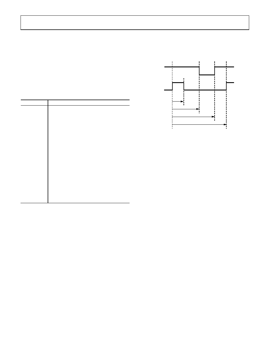
In all modes, the PWMxCOMx MMRs control the point at
which the PWM outputs change state. An example of the first
pair of PWM outputs (PWM0 and PWM1) is shown in Figure 40.
HIGH SIDE
(PWM0)
LOW SIDE
(PWM1)
PWM0COM2
PWM0COM1
PWM0COM0
PWM0LEN
08675-
056
Figure 40. PWM Timing
The PWM clock is selectable via PWMCON1 with one of the
following values: UCLK divided by 2, 4, 8, 16, 32, 64, 128, or
256. The length of a PWM period is defined by PWMxLEN.
The PWM waveforms are set by the count value of the 16-bit
timer and the compare registers contents, as shown with the
PWM0 and PWM1 waveforms in Figure 40.
The low-side waveform, PWM1, goes high when the timer
count reaches PWM0LEN, and it goes low when the timer
count reaches the value held in PWM0COM2 or when the
high-side waveform (PWM0) goes low.
The high-side waveform, PWM0, goes high when the timer
count reaches the value held in PWM0COM0, and it goes low
when the timer count reaches the value held in PWM0COM1.
PWMCON1 Control Register
Name:
PWMCON1
Address:
0xFFFF0F80
Default value:
0x0012
Access:
Read and write
Function:
This is a 16-bit MMR that configures the
PWM outputs.
Rev. E
相關(guān)PDF資料 |
PDF描述 |
|---|---|
| AIUR-10-182K | INDUCTOR POWER 1800UH 10% T/H |
| EYM15DRSD | CONN EDGECARD 30POS DIP .156 SLD |
| V300C3V3C50B | CONVERTER MOD DC/DC 3.3V 50W |
| AIUR-06-271K | INDUCTOR POWER 270UH 10% T/H |
| EGM15DRSD | CONN EDGECARD 30POS DIP .156 SLD |
相關(guān)代理商/技術(shù)參數(shù) |
參數(shù)描述 |
|---|---|
| EVAL-ADuC7023QSPZ2 | 制造商:AD 制造商全稱:Analog Devices 功能描述:Precision Analog Microcontroller, 12-Bit Analog I/O, ARM7TDMI MCU with Enhanced IRQ Handler |
| EVALADUC7023QSPZU1 | 制造商:Analog Devices 功能描述: |
| EVAL-ADUC7024QS | 制造商:Analog Devices 功能描述:QUICK START DEVELOPMENT SYSTEM - Bulk |
| EVAL-ADUC7024QS-U2 | 制造商:Analog Devices 功能描述:QUICK START DEVL SYST EVAL BOARD I.C. - Bulk |
| EVAL-ADUC7024QS-U3 | 制造商:Analog Devices 功能描述:ARM7 ADUC7024 QUICKSTART DEV KIT |
發(fā)布緊急采購(gòu),3分鐘左右您將得到回復(fù)。