- 您現(xiàn)在的位置:買賣IC網(wǎng) > PDF目錄383876 > T7256A Compliance with the New ETSI PSD Requirement PDF資料下載
參數(shù)資料
| 型號(hào): | T7256A |
| 英文描述: | Compliance with the New ETSI PSD Requirement |
| 中文描述: | 符合新的ETSI PSD的要求 |
| 文件頁數(shù): | 19/116頁 |
| 文件大?。?/td> | 1056K |
| 代理商: | T7256A |
第1頁第2頁第3頁第4頁第5頁第6頁第7頁第8頁第9頁第10頁第11頁第12頁第13頁第14頁第15頁第16頁第17頁第18頁當(dāng)前第19頁第20頁第21頁第22頁第23頁第24頁第25頁第26頁第27頁第28頁第29頁第30頁第31頁第32頁第33頁第34頁第35頁第36頁第37頁第38頁第39頁第40頁第41頁第42頁第43頁第44頁第45頁第46頁第47頁第48頁第49頁第50頁第51頁第52頁第53頁第54頁第55頁第56頁第57頁第58頁第59頁第60頁第61頁第62頁第63頁第64頁第65頁第66頁第67頁第68頁第69頁第70頁第71頁第72頁第73頁第74頁第75頁第76頁第77頁第78頁第79頁第80頁第81頁第82頁第83頁第84頁第85頁第86頁第87頁第88頁第89頁第90頁第91頁第92頁第93頁第94頁第95頁第96頁第97頁第98頁第99頁第100頁第101頁第102頁第103頁第104頁第105頁第106頁第107頁第108頁第109頁第110頁第111頁第112頁第113頁第114頁第115頁第116頁
Data Sheet
January 1998
T7256 Single-Chip NT1 (SCNT1) Transceiver
Lucent Technologies Inc.
15
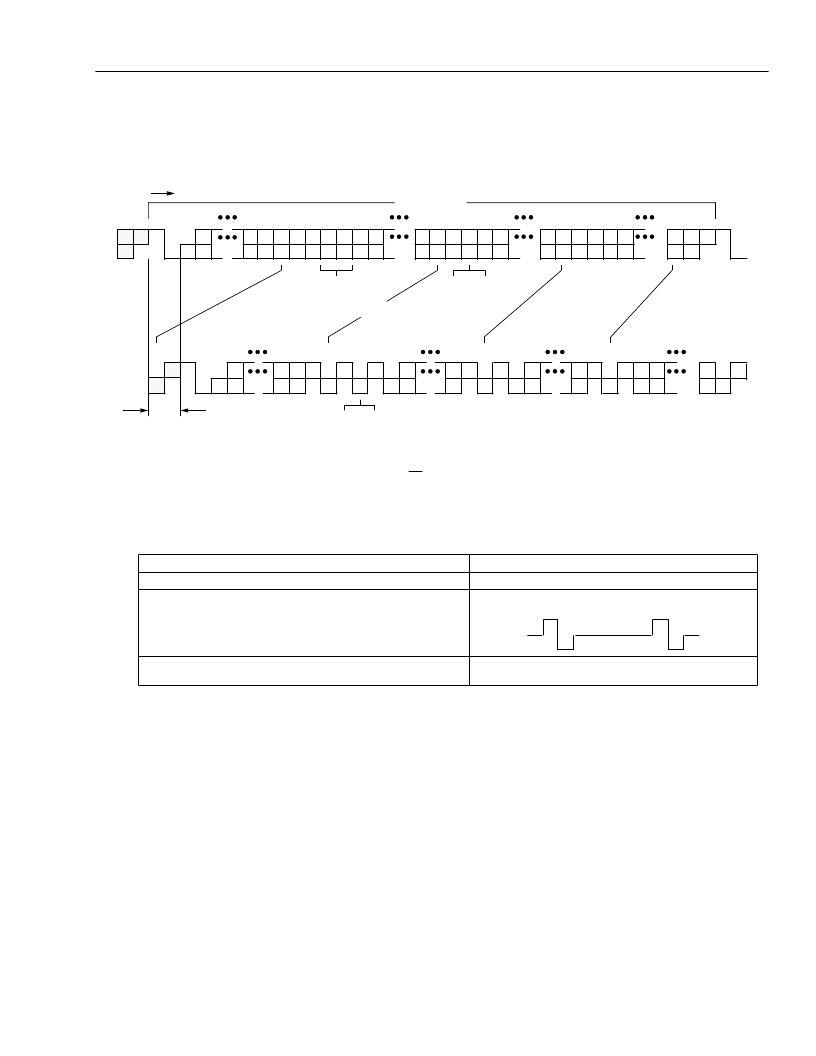
S/T-Interface Frame Structure
(continued)
In the TE-to-NT direction, in at least four of five frames, this second violation occurs within 13 bits of the F bit. If this
coding algorithm is not maintained, the receiver loses synchronization, but the T7256 continues transmitting.
F = Framing bit
L = dc balancing bit
D = D-channel bit
E = Echo D-channel bit
FA = Auxiliary framing bit or Q-channel bit
N = Bit set to binary value N = FA
A = Activation bit
S = S-channel bit
M = Multiframe synchronization bit
B1 = Bit within B channel 1
B2 = Bit within B channel 2
5-2480 (C)
Figure 7. Details of NT and TE Frames
Signals from NT to TE
Signals from TE to NT
No signal.
A continuous signal with the following pattern:
positive ZERO, negative ZERO, six ONEs.
INFO 0
INFO 2
No signal.
Frame with all bits of B, D, and D echo (E) channels set to
binary ZERO; bit A set to binary ZERO; N and L bits set ac-
cording to the normal coding rules.
INFO 0
INFO 1
INFO 4
Frames with operational data on B, D, and E channels; bit
A set to binary ONE.
INFO 3
Synchronized frames with operational data on B
and D channels.
48 1
+0
4
48 1
2
3
9 10 11 12 13 14 15 16 17
23 24 25 26 27 28
34 35 36 37 38 39
45 46 47 48 1
B1
L
F
L B1
B1 B1 E
D
A FA N B2 B2
B2 E
D
M B1 B1
B1 E
D
S B2 B2
B2 E
D
L
F
L
MULTIFRAME SYNC
BIT (OPTIONAL, ONCE
IN 20 FRAMES)
(NT TO TE)
2
10 11 12 13 14 15
23 24 25 26
34 35 36 37
45 46 47
B1
D
F
B1 L
D
L FA L
B2 L
D
L
B1 L
D
L
B2
B2 L
D
L
1
–0
L
3
4
16 17
B2 B2
27 28
B1 B1
38 39
B2
48
FA/N BIT PAIR
INVERT TO FLAG
Q-BIT TRANSMISSION
(TE TO NT)
Q-BIT OPTION
(EVERY 5TH FRAME)
2-bit OFFSET
48 bits IN 250
μ
s
TIME
相關(guān)PDF資料 |
PDF描述 |
|---|---|
| T7288 | CEPT/E1 Line Interface(CEPT/E1 線接口) |
| T7290A | DS1/T1/CEPT/E1 Line Interface(DS1/T1/CEPT/E1 線接口) |
| T7295-1 | E3 Integrated Line Receiver(E3 集成線接收器) |
| T7295-6 | DS3/SONET STS-1 Integrated Line Receiver(DS3/SONET STS-1 集成線接收器) |
| T7296 | Integrated Line Transmitter(集成PCM線傳送器) |
相關(guān)代理商/技術(shù)參數(shù) |
參數(shù)描述 |
|---|---|
| T7257 | 制造商:TE Connectivity 功能描述: |
| T-726 | 制造商:RHOMBUS-IND 制造商全稱:Rhombus Industries Inc. 功能描述:ADSL Line Interface Transformers |
| T7263 | 制造商:TE Connectivity 功能描述: |
| T7263A | 制造商:Toshiba America Electronic Components 功能描述:T7263A |
| T7264 | 制造商:TE Connectivity 功能描述: |
發(fā)布緊急采購,3分鐘左右您將得到回復(fù)。