- 您現(xiàn)在的位置:買賣IC網(wǎng) > PDF目錄379803 > CD1865 (Intel Corp.) Intelligent Eight-Channel Communications Controller PDF資料下載
參數(shù)資料
| 型號: | CD1865 |
| 廠商: | Intel Corp. |
| 英文描述: | Intelligent Eight-Channel Communications Controller |
| 中文描述: | 智能八通道通信控制器 |
| 文件頁數(shù): | 79/150頁 |
| 文件大小: | 871K |
| 代理商: | CD1865 |
第1頁第2頁第3頁第4頁第5頁第6頁第7頁第8頁第9頁第10頁第11頁第12頁第13頁第14頁第15頁第16頁第17頁第18頁第19頁第20頁第21頁第22頁第23頁第24頁第25頁第26頁第27頁第28頁第29頁第30頁第31頁第32頁第33頁第34頁第35頁第36頁第37頁第38頁第39頁第40頁第41頁第42頁第43頁第44頁第45頁第46頁第47頁第48頁第49頁第50頁第51頁第52頁第53頁第54頁第55頁第56頁第57頁第58頁第59頁第60頁第61頁第62頁第63頁第64頁第65頁第66頁第67頁第68頁第69頁第70頁第71頁第72頁第73頁第74頁第75頁第76頁第77頁第78頁當(dāng)前第79頁第80頁第81頁第82頁第83頁第84頁第85頁第86頁第87頁第88頁第89頁第90頁第91頁第92頁第93頁第94頁第95頁第96頁第97頁第98頁第99頁第100頁第101頁第102頁第103頁第104頁第105頁第106頁第107頁第108頁第109頁第110頁第111頁第112頁第113頁第114頁第115頁第116頁第117頁第118頁第119頁第120頁第121頁第122頁第123頁第124頁第125頁第126頁第127頁第128頁第129頁第130頁第131頁第132頁第133頁第134頁第135頁第136頁第137頁第138頁第139頁第140頁第141頁第142頁第143頁第144頁第145頁第146頁第147頁第148頁第149頁第150頁
Intelligent Eight-Channel Communications Controller
—
CD1865
Datasheet
79
However, when the system software design chooses to make use of the automatic Out-of-Band
Flow Control with the pins, then the signal naming convention no longer holds true in some cases,
depending on whether the device is used as DCE or DTE. In this case, it is best to think of the pins
in terms of their actual uses within the CD1865 and connect them accordingly, without regard to
their names. The RTS* and CTS* pins are associated with the transmitter and the DTR* and DSR*
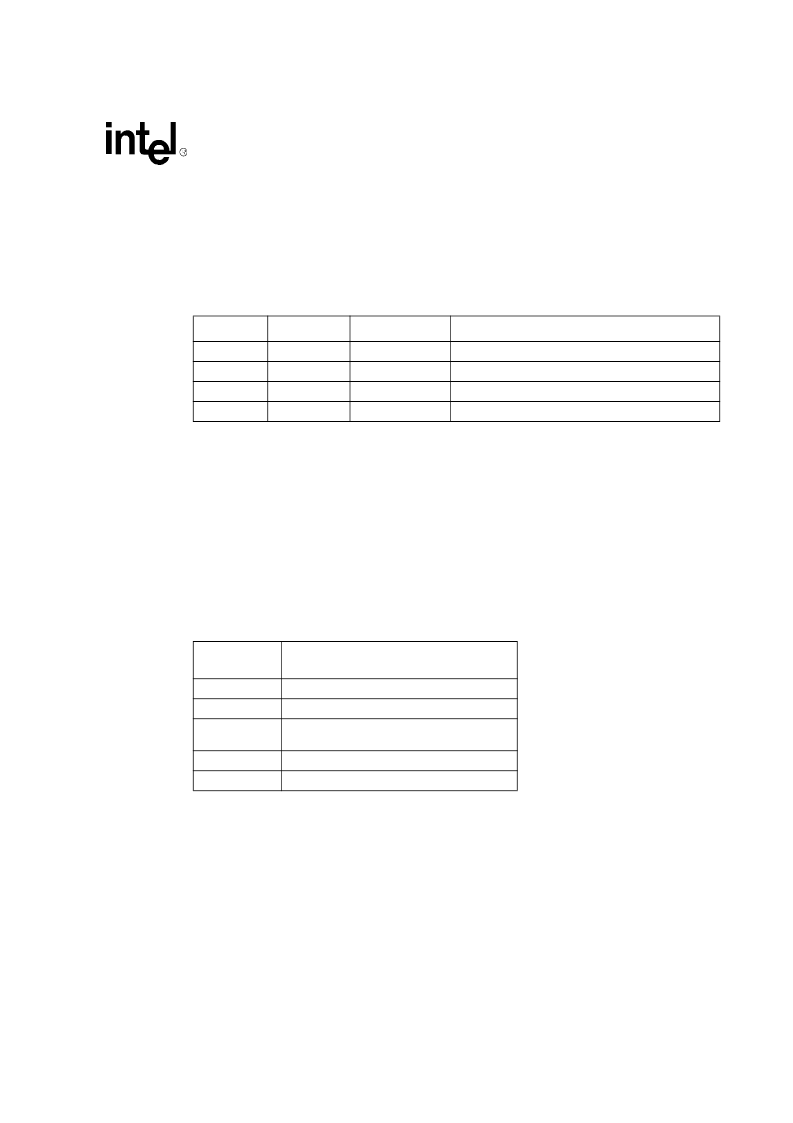
pins are associated with the receiver. The table below shows Intel
’
s recommended signal hook-up if
automatic, Out-of-Band Flow Control is required.
For example, if the CD1865 is designed to be a DCE and automatic Out-of-Band Flow Control is
required, the pin labeled DTR should be connected to remote CTS input. If the CD1865 is to be
used as the DTE side, then the CD1865 CTS output would be connected to the remote CTS input.
Note that if automatic Out-of-Band Flow Control is implemented, the activity of DTR and DSR
pins do not implement the function assigned to those signal names by the signalling conventions of
the CCITT and other standards organization. These names would only apply to these pins if they
are under program control and not under automatic CD1865 control. In fact, the
‘
DTR
’
function, as
defined, enables the modem to go on- and off-line, depending on the state of the pin. If automatic
control is used, then DTR would go inactive when the receive FIFO reached the programmed
threshold thus causing the modem to drop the connection (carrier) to the remote, which would not
be the correct function. Refer to
Section 7.3
for details on operation of modem pins in flow-control
applications.
Modem pins are implemented as I/O ports accessible by either the CD1865 processor or the host.
The modem pins are not connected directly to the transmit or receive hardware. When a user
programs out-of-band modem functions to be active, the CD1865 processor reads from and writes
to these pins. Specifically, when RTS* and CTS* are being used for transmit flow control, the
CD1865 processor asserts RTS* and senses CTS*, as required. Likewise, when configured to do
so, the Receive FIFO negates DTR* when full. The host should not be allowed to re-assert it
inadvertently. The host is not
‘
locked out
’
of accessing these bits; care should be taken so that these
bits are not written to, causing the system to malfunction.
The user has direct control over the RTS* and DTR* Outputs and can sense the state of CTS*,
CD*, and DSR* Inputs through the Modem Signal Value register (MSVR). Since the host is
accessing these pins directly, there is no delay in the host's ability to detect a level change. DTR*
and CD* depend on the state of the DTRSEL input.
DCE
DTE
CD1865 Pins
Out-of-Band Flow Control
CTS
DTR
Signal remote to transmit
RTS
Not implemented in this direction
RTS
RTS
Request remote permission to transmit
CTS
CTS
Enable transmitter
Modem
Control Pins
Function
RTS*
Request to Send (general-purpose output)
CTS*
Clear to Send (general-purpose input)
DTR*
Data Terminal Ready (carrier detect/general-
purpose input/output)
DSR*
Data Set Ready (general-purpose input)
CD*
Carrier Detect (general-purpose input)
相關(guān)PDF資料 |
PDF描述 |
|---|---|
| CD22100 | CMOS 4 x 4 Crosspoint Switch with Control Memory High-Voltage Type (20V Rating) |
| CD22100E | CMOS 4 x 4 Crosspoint Switch with Control Memory High-Voltage Type (20V Rating) |
| CD22100F | CMOS 4 x 4 Crosspoint Switch with Control Memory High-Voltage Type (20V Rating) |
| CD22101 | CMOS 4 x 4 x 2 Crosspoint Switch with Control Memory |
| CD22101E | CMOS 4 x 4 x 2 Crosspoint Switch with Control Memory |
相關(guān)代理商/技術(shù)參數(shù) |
參數(shù)描述 |
|---|---|
| CD1865N | 制造商:未知廠家 制造商全稱:未知廠家 功能描述:Analog IC |
| CD1865P | 制造商:未知廠家 制造商全稱:未知廠家 功能描述:Analog IC |
| CD1866N | 制造商:未知廠家 制造商全稱:未知廠家 功能描述:Analog IC |
| CD1866P | 制造商:未知廠家 制造商全稱:未知廠家 功能描述:Analog IC |
| CD1867N | 制造商:未知廠家 制造商全稱:未知廠家 功能描述:Analog IC |
發(fā)布緊急采購,3分鐘左右您將得到回復(fù)。