- 您現(xiàn)在的位置:買賣IC網(wǎng) > PDF目錄382686 > TSB12C01APZ (Texas Instruments, Inc.) High-Speed Serial-Bus Link-Layer Controller PDF資料下載
參數(shù)資料
| 型號(hào): | TSB12C01APZ |
| 廠商: | Texas Instruments, Inc. |
| 英文描述: | High-Speed Serial-Bus Link-Layer Controller |
| 中文描述: | 高速串行總線鏈路層控制器 |
| 文件頁數(shù): | 41/59頁 |
| 文件大小: | 275K |
| 代理商: | TSB12C01APZ |
第1頁第2頁第3頁第4頁第5頁第6頁第7頁第8頁第9頁第10頁第11頁第12頁第13頁第14頁第15頁第16頁第17頁第18頁第19頁第20頁第21頁第22頁第23頁第24頁第25頁第26頁第27頁第28頁第29頁第30頁第31頁第32頁第33頁第34頁第35頁第36頁第37頁第38頁第39頁第40頁當(dāng)前第41頁第42頁第43頁第44頁第45頁第46頁第47頁第48頁第49頁第50頁第51頁第52頁第53頁第54頁第55頁第56頁第57頁第58頁第59頁
5–1
5 Electrical Characteristics
5.1
Absolute Maximum Ratings Over Free-Air Temperature Range (Unless
Otherwise Noted)
Supply voltage range, V
CC
(see Note 1)
Input voltage range, at any input, V
I
Output voltage range, V
O
Input clamp current, I
IK
(V
I
< 0 or V
I
> V
CC
) (see Note 2)
Continuous total power dissipation
Output clamp current, I
OK
(V
O
< 0 or V
O
> V
CC
) (see Note 3)
Operating free-air temperature range, T
A
: A suffix
–0.5 V to 6 V
. . . . . . . . . . . . . . . . . . . . . . . . . . . .
. . . . . . . . . . . . . . . . . . . . . . . .
. . . . . . . . . . . . . . . . . . . . . . . . . . . . . . . . .
–0.5 V to V
CC
+ 0.5 V
–0.5 V to V
CC
+ 0.5 V
. . . . . . . . . . . . . . . . . .
See Maximum Dissipation Rating Table
. . . . . . . . . . . . . .
. . . . . . . . . . . . . . . . . . . . .
AI suffix
. . . . . . . . . . . . . . . . . .
AM suffix
. . . . . . . . . . . . . . . .
. . . . . . . . . . . . . . . . . . . . . . . . . . . . . . . . .
. . . . . . . . . . . . . . . . . . . . . . . . . . . . . . . . . . . . .
±
20 mA
. . . . . . . . . .
±
20 mA
0
°
C to 70
°
C
–40
°
C to 85
°
C
–55
°
C to 125
°
C
–65
°
C to 150
°
C
Storage temperature range, T
stg
Case temperature for 10 seconds, T
C
Stresses beyond those listed under “absolute maximum ratings” may cause permanent damage to the device. These
are stress ratings only, and functional operation of the device at these or any other conditions beyond those indicated
under “recommended operating conditions” is not implied. Exposure to absolute-maximum-rated conditions for
extended periods may affect device reliability.
NOTES:
1. All voltage values are with respect to GND.
2. This applies to all inputs.
3. This applies to all outputs.
260
°
C
MAXIMUM DISSIPATION RATING TABLE
PACKAGE
TA
≤
25
°
C
POWER RATING
DERATING
FACTOR
ABOVE TA = 25
°
C
16.9 mW/
°
C
19.2 mW/
°
C
TA = 70
°
C
POWER RATING
TA = 85
°
C
POWER RATING
TA = 125
°
C
POWER RATING
PZ
WN
2119 mW
2404 mW
1356 mW
1538 mW
1102 mW
1250 mW
—
481 mW
Power dissipation of package based on an absolute maximum junction temperature of 150
°
C.
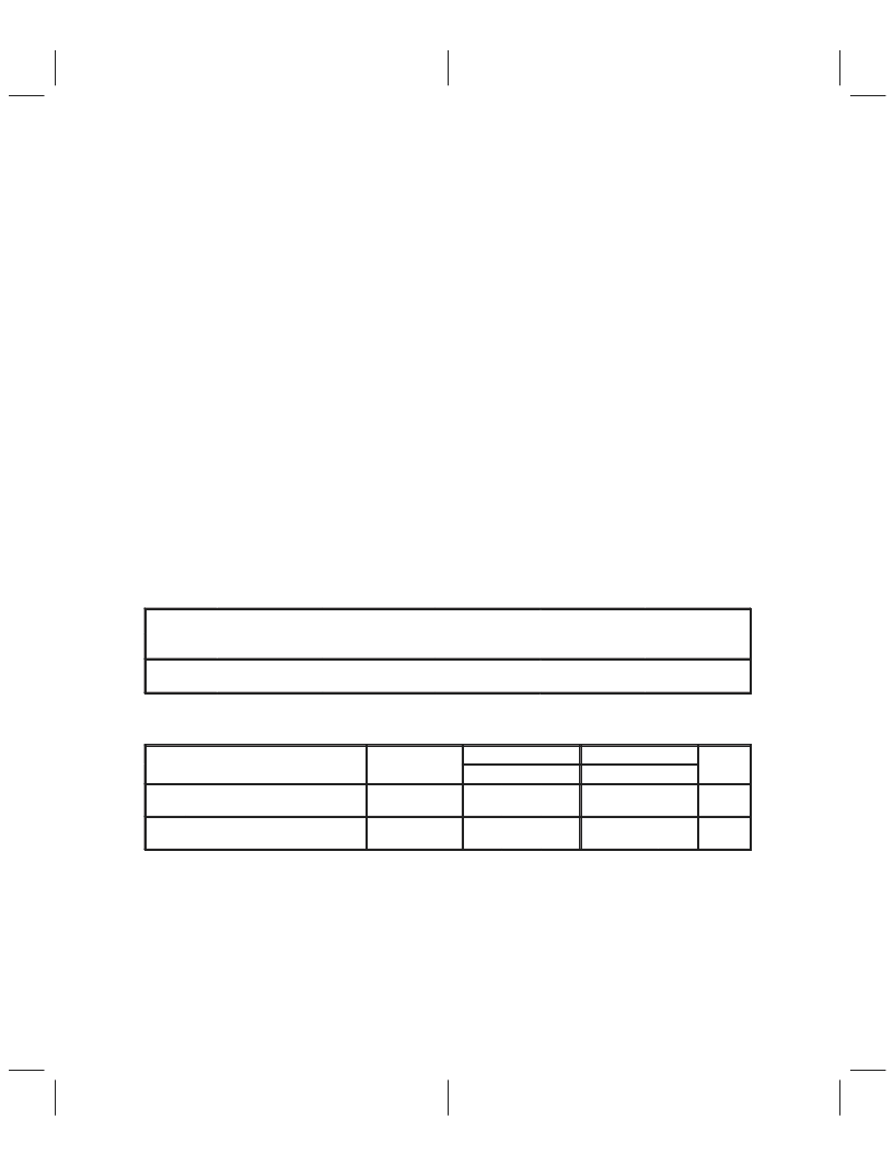
PACKAGE THERMAL CHARACTERISTICS§
PARAMETER
TEST
PZ PACKAGE
MIN
NOM
WN PACKAGE
MIN
NOM
UNIT
CONDITIONS
MAX
MAX
R
θ
JA
Junction-to-ambient thermal
impedance
Board mounted,
No air flow
59
52
°
C/W
R
θ
JC
Junction-to-case thermal
impedance
§Thermal characteristics very depending on die and leadframe pad size as well as mold compound. These values
represent typical die and pad sizes for the respective packages. The R value decreases as the die or pad sizes
increases. Thermal values represent PWB bands with minimal amounts of metal.
13
8
°
C/W
相關(guān)PDF資料 |
PDF描述 |
|---|---|
| TSB12C01AWN | High-Speed Serial-Bus Link-Layer Controller |
| TSB12LV01APZ | High-Speed Serial-Bus Link-Layer Controller |
| TSB3055 | IC APEX 20KE FPGA 300K 240-PQFP |
| TSB41AB3 | IC APEX 20KE FPGA 400K 672-FBGA |
| TSB41BA3-EP | IC APEX 20KE FPGA 400K 672-FBGA |
相關(guān)代理商/技術(shù)參數(shù) |
參數(shù)描述 |
|---|---|
| TSB12C01AWN | 制造商:TI 制造商全稱:Texas Instruments 功能描述:High-Speed Serial-Bus Link-Layer Controller |
| TSB12LV01A | 制造商:Texas Instruments 功能描述: |
| TSB12LV01AIPZ | 制造商:TI 制造商全稱:Texas Instruments 功能描述:IEEE 1394 (Firewire) Bus Interface/Controller |
| TSB12LV01APZ | 制造商:TI 制造商全稱:Texas Instruments 功能描述:High-Speed Serial-Bus Link-Layer Controller |
| TSB12LV01B | 制造商:TI 制造商全稱:Texas Instruments 功能描述:IEEE 1394-1995 HIGH SPEED SERIAL BUS LINK LAYER CONTROLLER |
發(fā)布緊急采購,3分鐘左右您將得到回復(fù)。