- 您現(xiàn)在的位置:買賣IC網(wǎng) > PDF目錄98081 > SII3531ACNU PCI BUS CONTROLLER, QCC48 PDF資料下載
參數(shù)資料
| 型號(hào): | SII3531ACNU |
| 元件分類: | 總線控制器 |
| 英文描述: | PCI BUS CONTROLLER, QCC48 |
| 封裝: | 7 X 7 MM, 0.40 MM PITCH, LEAD FREE, QFN-48 |
| 文件頁(yè)數(shù): | 53/81頁(yè) |
| 文件大小: | 532K |
| 代理商: | SII3531ACNU |
第1頁(yè)第2頁(yè)第3頁(yè)第4頁(yè)第5頁(yè)第6頁(yè)第7頁(yè)第8頁(yè)第9頁(yè)第10頁(yè)第11頁(yè)第12頁(yè)第13頁(yè)第14頁(yè)第15頁(yè)第16頁(yè)第17頁(yè)第18頁(yè)第19頁(yè)第20頁(yè)第21頁(yè)第22頁(yè)第23頁(yè)第24頁(yè)第25頁(yè)第26頁(yè)第27頁(yè)第28頁(yè)第29頁(yè)第30頁(yè)第31頁(yè)第32頁(yè)第33頁(yè)第34頁(yè)第35頁(yè)第36頁(yè)第37頁(yè)第38頁(yè)第39頁(yè)第40頁(yè)第41頁(yè)第42頁(yè)第43頁(yè)第44頁(yè)第45頁(yè)第46頁(yè)第47頁(yè)第48頁(yè)第49頁(yè)第50頁(yè)第51頁(yè)第52頁(yè)當(dāng)前第53頁(yè)第54頁(yè)第55頁(yè)第56頁(yè)第57頁(yè)第58頁(yè)第59頁(yè)第60頁(yè)第61頁(yè)第62頁(yè)第63頁(yè)第64頁(yè)第65頁(yè)第66頁(yè)第67頁(yè)第68頁(yè)第69頁(yè)第70頁(yè)第71頁(yè)第72頁(yè)第73頁(yè)第74頁(yè)第75頁(yè)第76頁(yè)第77頁(yè)第78頁(yè)第79頁(yè)第80頁(yè)第81頁(yè)
PCI Express to Serial ATA Controller
Data Sheet
Silicon Image, Inc.
2006 Silicon Image, Inc.
SiI-DS-0208-C
57
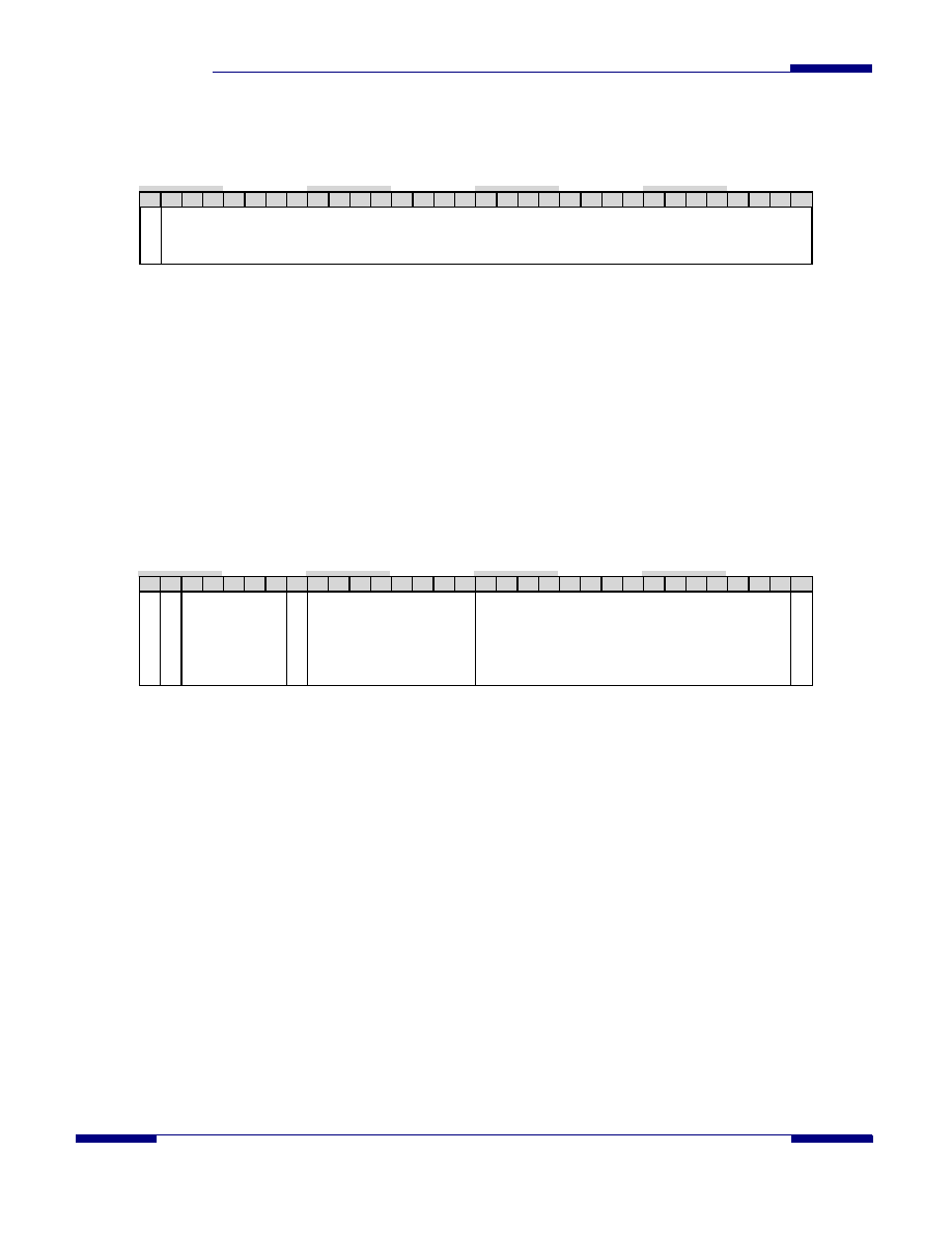
6.2.1
Port Slot Status Register
Address Offset: 00H
Access Type: Read
Reset Value: 0x0000_0000
31 30 29 28 27 26 25 24 23 22 21 20 19 18 17 16 15 14 13 12 11 10 09 08 07 06 05 04 03 02 01 00
Attention
Slot Status
This register provides the Status for the 31 Command Slots for the port. This register also appears in Port register space.
Reading this register will clear the Command Completion Status for the port if the Interrupt No Clear on Read bit (bit 3) of the
Port Control register is 0. The register bits are defined below.
Bit [31]: Attention (R) – This bit indicates that something occurred that requires the attention of the host. Other port
registers must be examined to determine the origin of the error. This bit is the logical OR of the masked interrupt
conditions, except for Command Completion, reported in the Port Interrupt Status register.
Bit [30:0]: Slot Status (R) – These bits are the Active status bits corresponding to Slot numbers 30 to 0. The Active
status bit for a slot is set when the Slot number is written to the Command Execution FIFO (direct command transfer
method) or when a Command Activation register is written (indirect command transfer method).
6.2.2
Global Control
Address Offset: 40H
Access Type: Read/Write
Reset Value: 0x8100_0000
31 30 29 28 27 26 25 24 23 22 21 20 19 18 17 16 15 14 13 12 11 10 09 08 07 06 05 04 03 02 01 00
Global
Re
set
MS
IACK
Reserved
3Gb/s
C
a
pable
Arbiter Control
Reserved
Port
Int
Enable
This register controls various functions of the chip.
Bit [31]: Global Reset (R/W). This bit, when set to one, asserts a port reset to all ports. This bit must be cleared to
zero to allow normal operation. Once set by this bit, all port resets will remain set to one until explicitly cleared to
zero through the individual port control clear registers. Refer to the port control set register description for more
information.
Bit [30]: MSI Acknowledge (W). Writing a one to this bit acknowledges a Message Signaled Interrupt and permits
generation of another MSI. This bit is cleared immediately after the acknowledgement is recognized by the control
logic, hence the bit will always be read as a zero. If all interrupt conditions are removed subsequent to an MSI, it is
not necessary to assert this Acknowledge; another MSI will be generated when an interrupt condition occurs.
Bit [29:25,15:1]: Reserved (R). These bits are reserved and will return zeroes when read.
Bit [23:16]: Arbiter Control (R/W). This bit field, when set to 42H, selects an alternate arbitration algorithm.
Bit [24]: 3Gb/s Capable (R). This bit is always one to indicate that the device is configured and tested for 3Gb/s (S-
ATA generation 2) operation.
Bit [0]: Port Interrupt Enable (R/W). This bit, when set to one, allows assertion of an interrupt when the port asserts
an interrupt. When set to zero, the port interrupts are masked.
相關(guān)PDF資料 |
PDF描述 |
|---|---|
| SIO10N268-NU | MULTIFUNCTION PERIPHERAL, PQFP128 |
| SIS300 | GRAPHICS PROCESSOR, PBGA365 |
| SK12430PJT | 800 MHz, OTHER CLOCK GENERATOR, PQCC28 |
| SK12439PJ | 800 MHz, OTHER CLOCK GENERATOR, PQCC28 |
| SK12439PJT | 800 MHz, OTHER CLOCK GENERATOR, PQCC28 |
相關(guān)代理商/技術(shù)參數(shù) |
參數(shù)描述 |
|---|---|
| SII3611 | 制造商:SILICONIMAGE 制造商全稱:SILICONIMAGE 功能描述:SATALink Device Bridge |
| SII3611CT80-1.5 | 制造商:SILICON IMAGE 功能描述:3611CT80-1.5 |
| SII3723 | 制造商:SILICONIMAGE 制造商全稱:SILICONIMAGE 功能描述:Third Generation SATA Port Multiplier Storage Processor |
| SiI3723CNU | 制造商:Silicon Image Inc 功能描述: |
| SII3726 | 制造商:SILICONIMAGE 制造商全稱:SILICONIMAGE 功能描述:SATA Port Multiplier |
發(fā)布緊急采購(gòu),3分鐘左右您將得到回復(fù)。