- 您現(xiàn)在的位置:買賣IC網(wǎng) > PDF目錄360517 > 7560 7560 Group Datasheet Datasheet 1682K/JAN.14.03 PDF資料下載
參數(shù)資料
| 型號: | 7560 |
| 英文描述: | 7560 Group Datasheet Datasheet 1682K/JAN.14.03 |
| 中文描述: | 7560組數(shù)據(jù)表數(shù)據(jù)表1682K/JAN.14.03 |
| 文件頁數(shù): | 27/90頁 |
| 文件大?。?/td> | 1682K |
| 代理商: | 7560 |
第1頁第2頁第3頁第4頁第5頁第6頁第7頁第8頁第9頁第10頁第11頁第12頁第13頁第14頁第15頁第16頁第17頁第18頁第19頁第20頁第21頁第22頁第23頁第24頁第25頁第26頁當(dāng)前第27頁第28頁第29頁第30頁第31頁第32頁第33頁第34頁第35頁第36頁第37頁第38頁第39頁第40頁第41頁第42頁第43頁第44頁第45頁第46頁第47頁第48頁第49頁第50頁第51頁第52頁第53頁第54頁第55頁第56頁第57頁第58頁第59頁第60頁第61頁第62頁第63頁第64頁第65頁第66頁第67頁第68頁第69頁第70頁第71頁第72頁第73頁第74頁第75頁第76頁第77頁第78頁第79頁第80頁第81頁第82頁第83頁第84頁第85頁第86頁第87頁第88頁第89頁第90頁

SINGLE-CHIP 8-BIT CMOS MICROCOMPUTER
MITSUBISHI MICROCOMPUTERS
7560 Group
26
Key Input Interrupt (Key-on Wake Up)
The key input interrupt is enabled when any of port P2 is set to in-
put mode and the bit corresponding to key input control register is
set to
“
1
”
.
A Key input interrupt request is generated by applying
“
L
”
level
voltage to any pin of port P2 of which key input interrupt is en-
abled. In other words, it is generated when AND of input level
goes from
“
1
”
to
“
0
”
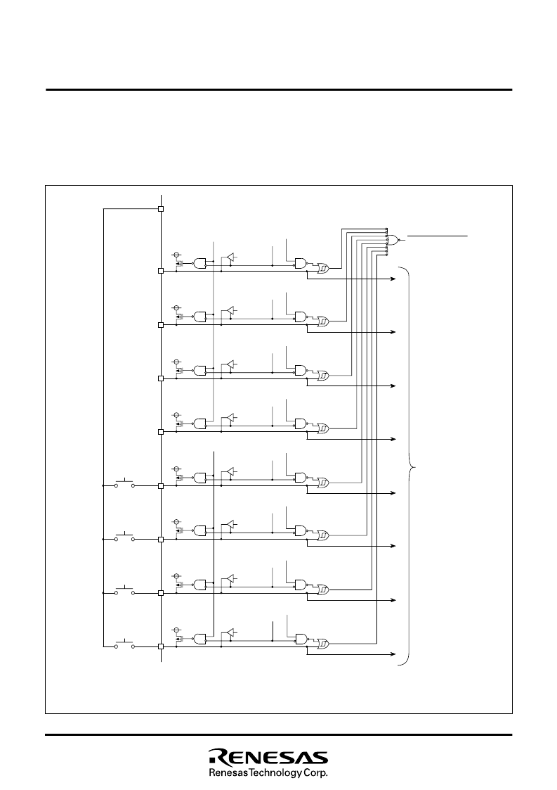
. A connection example of using a key input in-
terrupt is shown in Figure 22, where an interrupt request is gener-
ated by pressing one of the keys consisted as an active-low key
matrix which inputs to ports P2
0
–
P2
3
.
Fig. 22 Connection example when using key input interrupt and port P2 block diagram
P
l
a
o
r
t
h
P
2
0
t
c
P
d
o
i
r
e
t
c
P
t
i
2
0
o
r
n
r
e
g
i
s
t
e
r
=
“
0
”
P
l
a
o
r
t
h
P
2
1
t
c
Port P2
direction register =
“
0
”
P
l
a
o
r
t
h
P
2
2
t
c
Port P2
direction register =
“
0
”
Port P2
3
latch
Port P2
3
direction register =
“
0
”
Port P2
4
latch
Port P2
4
direction register =
“
1
”
Port P2
5
latch
Port P2
direction register =
“
1
”
P
l
a
o
r
t
h
P
2
6
t
c
P
d
o
i
r
e
t
c
P
t
i
2
6
o
r
n
r
e
g
i
s
t
e
r
=
“
1
”
Port P2
7
latch
Port P2
7
direction register =
“
1
”
P
2
0
i
n
p
u
t
P2
1
input
P2
2
input
P
2
3
i
n
p
u
t
P
2
4
o
u
t
p
u
t
P
2
5
o
u
t
p
u
t
P
2
6
o
u
t
p
u
t
P
2
7
o
u
t
p
u
t
P
U
L
L
r
e
g
i
s
t
B
e
r
i
A
7
t
Port P2
Input reading circuit
P
“
L
o
r
t
l
e
P
v
X
e
x
o
”
l
u
t
p
u
t
CMOS output buffer
P-channel transistor for pull-up
K
e
y
i
n
p
u
t
i
n
t
e
r
r
u
p
t
r
e
q
u
e
s
t
P2
7
key input control bit
P
2
6
k
e
y
i
n
p
u
t
c
o
n
t
r
o
l
b
i
t
P
2
5
k
e
y
i
n
p
u
t
c
o
n
t
r
o
l
b
i
t
P
2
4
k
e
y
i
n
p
u
t
c
o
n
t
r
o
l
b
i
t
P
2
3
k
e
y
i
n
p
u
t
c
o
n
t
r
o
l
b
i
t
=
“
1
”
P
U
L
L
r
B
e
i
g
t
i
6
s
t
=
e
r
“
1
A
”
P
2
2
k
e
y
i
n
p
u
t
c
o
n
t
r
o
l
b
i
t
=
“
1
”
P
2
1
k
e
y
i
n
p
u
t
c
o
n
t
r
o
l
b
i
t
=
“
1
”
P2
0
key input control bit =
“
1
”
相關(guān)PDF資料 |
PDF描述 |
|---|---|
| 7561Z0001S13 | READER PANEL MOUNT |
| 7561Z0001S13LF | READER PANEL MOUNT |
| 7561Z0001S14 | READER PANEL MOUNT |
| 7561Z0001S14LF | READER PANEL MOUNT |
| 7561Z0001S15 | READER PANEL MOUNT |
相關(guān)代理商/技術(shù)參數(shù) |
參數(shù)描述 |
|---|---|
| 7560 6 43 01 D | 制造商:Hummel 功能描述:Bulk |
| 7560 6 51 01 D | 制造商:Hummel 功能描述: |
| 7560_03 | 制造商:RENESAS 制造商全稱:Renesas Technology Corp 功能描述:SINGLE-CHIP 8-BIT CMOS MICROCOMPUTER |
| 7560_0308 | 制造商:RENESAS 制造商全稱:Renesas Technology Corp 功能描述:Difference among various products |
| 7-5-600 | 功能描述:3M 600 SCOTCH TRANSPARENT FILM T 制造商:3m (tc) 系列:600 零件狀態(tài):在售 標準包裝:1 |
發(fā)布緊急采購,3分鐘左右您將得到回復(fù)。