- 您現(xiàn)在的位置:買賣IC網(wǎng) > PDF目錄98068 > S1C62920D 4-BIT, MROM, 1.3 MHz, MICROCONTROLLER, UUC63 PDF資料下載
參數(shù)資料
| 型號(hào): | S1C62920D |
| 元件分類: | 微控制器/微處理器 |
| 英文描述: | 4-BIT, MROM, 1.3 MHz, MICROCONTROLLER, UUC63 |
| 封裝: | DIE-63 |
| 文件頁(yè)數(shù): | 35/78頁(yè) |
| 文件大?。?/td> | 874K |
| 代理商: | S1C62920D |
第1頁(yè)第2頁(yè)第3頁(yè)第4頁(yè)第5頁(yè)第6頁(yè)第7頁(yè)第8頁(yè)第9頁(yè)第10頁(yè)第11頁(yè)第12頁(yè)第13頁(yè)第14頁(yè)第15頁(yè)第16頁(yè)第17頁(yè)第18頁(yè)第19頁(yè)第20頁(yè)第21頁(yè)第22頁(yè)第23頁(yè)第24頁(yè)第25頁(yè)第26頁(yè)第27頁(yè)第28頁(yè)第29頁(yè)第30頁(yè)第31頁(yè)第32頁(yè)第33頁(yè)第34頁(yè)當(dāng)前第35頁(yè)第36頁(yè)第37頁(yè)第38頁(yè)第39頁(yè)第40頁(yè)第41頁(yè)第42頁(yè)第43頁(yè)第44頁(yè)第45頁(yè)第46頁(yè)第47頁(yè)第48頁(yè)第49頁(yè)第50頁(yè)第51頁(yè)第52頁(yè)第53頁(yè)第54頁(yè)第55頁(yè)第56頁(yè)第57頁(yè)第58頁(yè)第59頁(yè)第60頁(yè)第61頁(yè)第62頁(yè)第63頁(yè)第64頁(yè)第65頁(yè)第66頁(yè)第67頁(yè)第68頁(yè)第69頁(yè)第70頁(yè)第71頁(yè)第72頁(yè)第73頁(yè)第74頁(yè)第75頁(yè)第76頁(yè)第77頁(yè)第78頁(yè)

32
EPSON
S1C62920 TECHNICAL MANUAL
CHAPTER 4: PERIPHERAL CIRCUITS AND OPERATION (Clock Timer)
4.8 Clock Timer
4.8.1 Configuration of clock timer
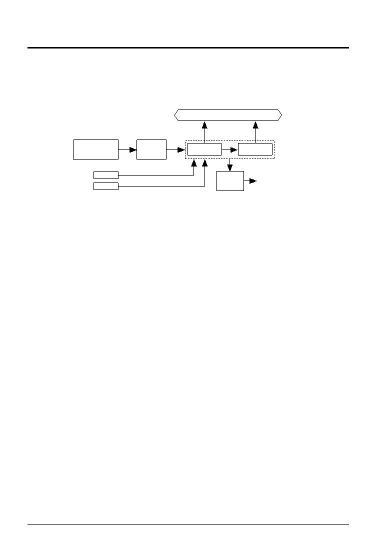
The S1C62920 has a built-in clock timer with OSC1 divided clock (256 Hz) as clock source. The clock timer
is configured of a 8-bit binary counter and the timer data (128–16 Hz and 8–1 Hz) can be read out by the
software.
Figure 4.8.1.1 is the block diagram for the clock timer.
Fig. 4.8.1.1 Block diagram for the clock timer
Ordinarily, this clock timer is used for all types of timing functions such as clocks.
4.8.2 Data reading and hold function
The 8 bits timer data are allocated to the address C9H and CAH.
C9H
D0: TM0 (128 Hz)
D1: TM1 (64 Hz)
D2: TM2 (32 Hz)
D3: TM3 (16 Hz)
CAH
D0: TM4 (8 Hz)
D1: TM5 (4 Hz)
D2: TM6 (2 Hz)
D3: TM7 (1 Hz)
Since the clock timer data has been allocated to two addresses, a carry is generated from the low-order data
within the count (TM0–TM3: 128–16 Hz) to the high-order data (TM4–TM7: 8–1 Hz). When this carry is
generated between the reading of the low-order data and the high-order data, a content combining the two
does not become the correct value (the low-order data is read as 0FH and the high-order data becomes the
value that is counted up 1 from that point).
The high-order data hold function in the S1C62920 is designed to operate to avoid this. This function
temporarily stops the counting up of the high-order data (by carry from the low-order data) at the point
where the low-order data has been read and consequently the time during which the high-order data is
held is the shorter of the two indicated here following.
1. Period until it reads the high-order data.
2. 0.48–1.5 msec (varies due to the timing of the reading)
Note: When the high-order data has previously been read, since the low-order data is not held, you should
be sure to first read from the low-order data.
4.8.3 Interrupt function
The clock timer can cause interrupts at the falling edge of 32 Hz, 8 Hz and 2 Hz signals. Software can set
whether to mask any of these frequencies.
Figure 4.8.3.1 is the timing chart of the clock timer.
128 Hz–16 Hz
Data bus
32 Hz, 8 Hz, 2 Hz
256 Hz
Clock timer reset signal
Interrupt request
Interrupt
control
8 Hz–1 Hz
Clock timer
TMRST
TMRUN
fOSC1
OSC1
oscillation circuit
Clock timer RUN/STOP signal
Dividing
circuit
相關(guān)PDF資料 |
PDF描述 |
|---|---|
| S1C62A33D | 4-BIT, MROM, 0.6 MHz, MICROCONTROLLER, UUC86 |
| S1C62N82F | 4-BIT, MROM, 0.032 MHz, MICROCONTROLLER, PQFP80 |
| S1C63158F0A0100 | 4-BIT, FLASH, 4.2 MHz, MICROCONTROLLER, PQFP100 |
| S1C63358F0A0100 | 4-BIT, MROM, 4.1 MHz, MICROCONTROLLER, PQFP100 |
| S1C63406F | 4-BIT, MROM, 4.2 MHz, MICROCONTROLLER, PQFP128 |
相關(guān)代理商/技術(shù)參數(shù) |
參數(shù)描述 |
|---|---|
| S1C63004 | 制造商:EPSON 制造商全稱:EPSON 功能描述:CMOS 4-bit Single Chip Microcontroller |
| S1C63008 | 制造商:EPSON 制造商全稱:EPSON 功能描述:CMOS 4-bit Single Chip Microcontroller |
| S1C63016 | 制造商:EPSON 制造商全稱:EPSON 功能描述:CMOS 4-bit Single Chip Microcontroller |
| S1C63158 | 制造商:EPSON 制造商全稱:EPSON 功能描述:4-bit Single Chip Microcomputer |
| S1C63408 | 制造商:EPSON 制造商全稱:EPSON 功能描述:4-bit Single Chip Microcomputer |
發(fā)布緊急采購(gòu),3分鐘左右您將得到回復(fù)。