- 您現(xiàn)在的位置:買賣IC網(wǎng) > PDF目錄385396 > HSP50214VC (INTERSIL CORP) Programmable Downconverter PDF資料下載
參數(shù)資料
| 型號: | HSP50214VC |
| 廠商: | INTERSIL CORP |
| 元件分類: | 通信及網(wǎng)絡 |
| 英文描述: | Programmable Downconverter |
| 中文描述: | SPECIALTY TELECOM CIRCUIT, PQFP120 |
| 封裝: | MQFP-120 |
| 文件頁數(shù): | 13/54頁 |
| 文件大小: | 395K |
| 代理商: | HSP50214VC |
第1頁第2頁第3頁第4頁第5頁第6頁第7頁第8頁第9頁第10頁第11頁第12頁當前第13頁第14頁第15頁第16頁第17頁第18頁第19頁第20頁第21頁第22頁第23頁第24頁第25頁第26頁第27頁第28頁第29頁第30頁第31頁第32頁第33頁第34頁第35頁第36頁第37頁第38頁第39頁第40頁第41頁第42頁第43頁第44頁第45頁第46頁第47頁第48頁第49頁第50頁第51頁第52頁第53頁第54頁

13
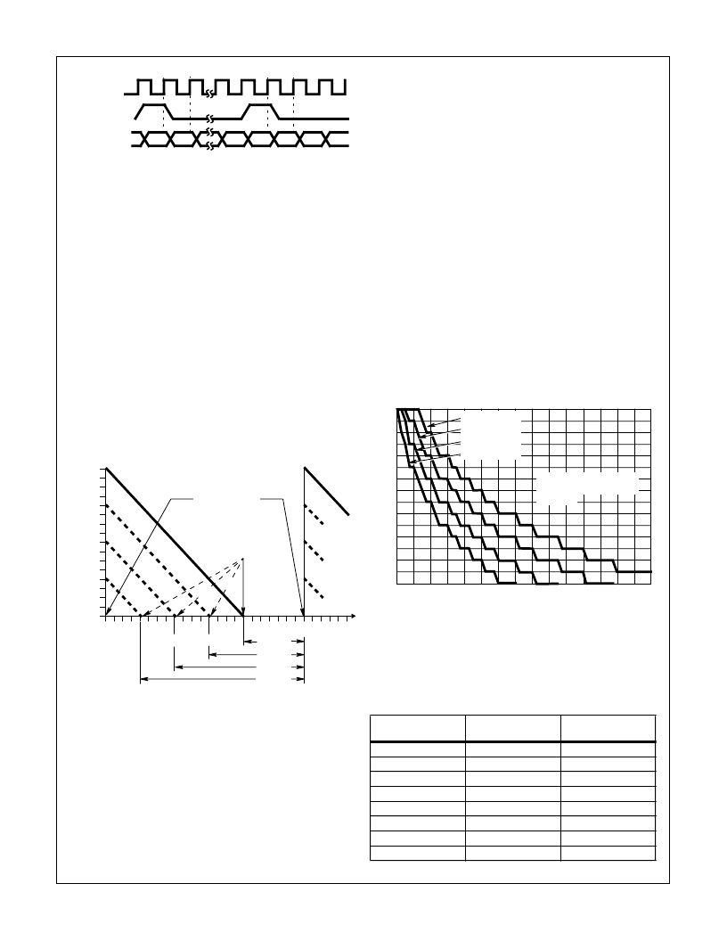
Each serial word has a programmable word width of either 8,
16, 24, or 32 bits (See Control Word 0, bits 4 and 5, for the
Carrier NCO programming and Control Word 11, bits 3 and
4, for Timing NCO programming). On the rising edge of the
clock, data on COF or SOF is clocked into an input shift reg-
ister. The beginning of a serial word is designated by assert-
ing either COFSYNC or SOFSYNC “high” one CLK period
prior to the first data bit.
The assertion of the COFSYNC (or SOFSYNC) starts a count
down from the programmed word width. On following CLKs,
data is shifted into the register until the specified number of
bits have been input. At this point the contents of the register
are transferred from the shift register to the respective 32-bit
holding register. The shift register can accept new data on the
following CLK. If the serial input word is defined to be less
than 32 bits, it will be transferred to the MSBs of the 32-bit
holding register and the LSBs of the holding register will be
zeroed. See Figure 14 for details.
NOTE: Serial Data must be loaded MSB first, and COFSYNC or
SOFSYNC should not be asserted for more than one CLK
cycle.
NOTE: COF loading and timing is relative to CLKIN while SOF
loading and timing is relative to PROCCLK.
NOTE: T
D
can be 0, and the fastest rate is with 8-bit word width.
CIC Decimation Filter
The mixer output may be filtered with the CIC filter or it may be
routed directly to the halfband filters. The CIC filter is used to
reduce the sample rate of a wideband signal to a rate that the
halfbands and programmable filters can process, given the
maximum computation speed of PROCCLK. (See Halfband
and FIR Filter Sections for techniques to calculate this value.)
Prior to the CIC filter, the output of the mixer goes through a
barrel shifter. The shifter is used to adjust the gain in 6dB
steps to compensate for the variation in filter gain with deci-
mation. (See Equation 6). Fine gain adjustments must be
done in the AGC section. The shifter is controlled by the sum
of a 4-bit CIC Shift Gain word from the microprocessor and a
3-bit gain word from the GAINADJ(2:0) pins. The three bit
value is pipelined to match the delay of the input samples.
The sum of the 3 and 4-bit shift gain words saturates at a
value of 15. Table 3 details the permissible values for the
GAINADJ(2:0) barrel shifter control, while the Figure 15
shows the permissible CIC Shift Gain values.
The CIC filter structure for the HSP50214 is fifth order; that
is it has five integrator/comb pairs. A fifth order CIC has
84dB of alias attenuation for output frequencies below 1/8
the CIC output sample rate.
The decimation rate of the CIC filter is programmed in Control
Word 0, bits 12 - 7. The CIC Shift Gain is programmed in Con-
trol Word 0, bits 16-13. The CIC Bypass is set in Control Word
0, bit 6.
COF/
SOF
MSB
MSB
CLKIN
COFSYNC/
SOFSYNC
LSB
OTE:
Data must be loaded MSB first.
IGURE 13. SERIAL INPUT TIMING FOR COF AND SOF INPUTS
Serial word width can be: 8, 16, 24, 32 bits wide.
T
D
is determined by the COFSYNC, COFSYNC rate.
FIGURE 14. HOLDING REGISTERS LOAD SEQUENCE FOR
COF AND SOF SERIAL OFFSET FREQUENCY
DATA
32
30
28
26
24
22
20
18
16
14
12
10
8
54
50
46
42
38
T
D
T
D
T
D
T
D
34
30
26
22
18
14
10
6
2
6
4
2
0
S
DATA TRANSFERRED
TO HOLDING REGISTER
CLK TIMES
ASSERTION OF
COFSYNC, SOFSYNC
(8)
(32)
(16)
(24)
TABLE 3. GAIN ADJUST CONTROL AND CIC DECIMATION
GAIN VALUE
(dB)
GAIN ADJ(2:0)
0
000
6
001
12
010
18
011
24
100
30
101
36
110
42
111
MAX. CIC
DECIMATION
32
27
24
21
18
16
12
10
FIGURE 15. CIC SHIFT GAIN VALUES
15
13
12
11
10
9
8
7
6
5
3
2
1
0
16
4
40
32
24
64
56
48
DECIMATION (R)
C14
8
12
20
28
36
44
52
60
8-BIT INPUT
10-BIT INPUT
12-BIT INPUT
14-BIT INPUT
ALLOWABLE CIC SHIFT
GAINS ARE BELOW THE
CURVES
HSP50214
相關PDF資料 |
PDF描述 |
|---|---|
| HSP50214VI | Programmable Downconverter |
| HSP50214 | Programmable Downconverter |
| HSP50215VC | Digital UpConverter |
| HSP50215VI | Digital UpConverter |
| HSP50215EVAL | DSP Modulator Evaluation Board |
相關代理商/技術參數(shù) |
參數(shù)描述 |
|---|---|
| HSP50214VI | 制造商:Rochester Electronics LLC 功能描述:- Bulk |
| HSP50215 | 制造商:INTERSIL 制造商全稱:Intersil Corporation 功能描述:DSP Modulator Evaluation Board |
| HSP50215EVAL | 制造商:INTERSIL 制造商全稱:Intersil Corporation 功能描述:DSP Modulator Evaluation Board |
| HSP50215VC | 制造商:INTERSIL 制造商全稱:Intersil Corporation 功能描述:Digital UpConverter |
| HSP50215VI | 制造商:INTERSIL 制造商全稱:Intersil Corporation 功能描述:Digital UpConverter |
發(fā)布緊急采購,3分鐘左右您將得到回復。