- 您現(xiàn)在的位置:買賣IC網(wǎng) > PDF目錄384806 > OXCB950 (Electronic Theatre Controls, Inc.) Integrated High Performance UART Cardbus / PCI interface PDF資料下載
參數(shù)資料
| 型號(hào): | OXCB950 |
| 廠商: | Electronic Theatre Controls, Inc. |
| 英文描述: | Integrated High Performance UART Cardbus / PCI interface |
| 中文描述: | 綜合高性能的UART Cardbus / PCI接口 |
| 文件頁數(shù): | 38/68頁 |
| 文件大小: | 409K |
| 代理商: | OXCB950 |
第1頁第2頁第3頁第4頁第5頁第6頁第7頁第8頁第9頁第10頁第11頁第12頁第13頁第14頁第15頁第16頁第17頁第18頁第19頁第20頁第21頁第22頁第23頁第24頁第25頁第26頁第27頁第28頁第29頁第30頁第31頁第32頁第33頁第34頁第35頁第36頁第37頁當(dāng)前第38頁第39頁第40頁第41頁第42頁第43頁第44頁第45頁第46頁第47頁第48頁第49頁第50頁第51頁第52頁第53頁第54頁第55頁第56頁第57頁第58頁第59頁第60頁第61頁第62頁第63頁第64頁第65頁第66頁第67頁第68頁
7.6.2
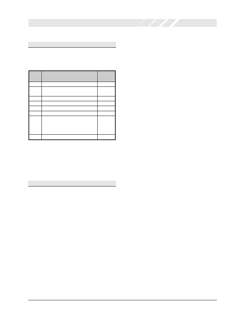
The source of the highest priority interrupt pending is
indicated by the contents of the Interrupt Status Register
‘ISR’. There are nine sources of interrupt at sx levels of
priority (1 is the highest) as shown in Table 18.
Level
Interrupt source
Data Sheet Revision 1.1
Page 38
OXCB950
OXFORD SEMICONDUCTOR LTD.
Interrupt Status Register ‘ISR’
ISR[5:0]
see note 3
-
1
No interrupt pending
1
Receiver status error
or
Address-bit detected in 9-bit mode
Receiver data available
Receiver time-out
Transmtter THR empty
Modemstatus change
In-band flow control XOFF
or
Special character (XOFF2)
or
Special character 1, 2, 3 or 4
or
bit 9 set in 9-bit mode
CTS or RTS change of state
000001
000110
2a
2b
3
4
5
2
000100
001100
000010
000000
010000
6
2
100000
Table 18: Interrupt Status Identification Codes
Note1:
Note2:
ISR[0] indicates whether any interrupts are pending.
Interrupts of priority levels 5 and 6 cannot occur unless the
UART is in Enhanced mode.
ISR[5] is only used in 650 & 950 modes. In 750 mode, it is ‘0’
when FIFO size is 16 and ‘1’ when FIFO size is 128. In all
other modes it is permanently set to 0
Note3:
7.6.3
Level 1:
Receiver status error interrupt (ISR[5:0]=’000110’):
Normal (non-9-bit) mode:
This interrupt is active whenever any of LSR[1], LSR[2],
LSR[3] or LSR[4] are set. These flags are cleared following
a read of the LSR. This interrupt is masked with IER[2].
9-bit mode:
This interrupt is active whenever any of LSR[1], LSR[2],
LSR[3] or LSR[4] are set. The receiver error interrupt due
to LSR[1], LSR[3] and LSR[4] is masked with IER[3]. The
‘a(chǎn)ddress-bit’ received interrupt is masked with NMR[1]. The
software driver can differentiate between receiver status
error and received address-bit (9
th
data bit) interrupt by
examning LSR[1] and LSR[7]. In 9-bit mode LSR[7] is only
set when LSR[3] or LSR[4] is set and it is not affected by
LSR[2] (i.e. 9
th
data bit).
Interrupt Description
Level 2a:
Receiver data available interrupt (ISR[5:0]=’000100’):
This interrupt is active whenever the receiver FIFO level is
above the interrupt trigger level.
Level 2b:
Receiver time-out interrupt (ISR[5:0]=’001100’):
A receiver time-out event, which may cause an interrupt,
will occur when all of the following conditions are true:
The UART is in a FIFO mode
There is data in the RHR.
There has been no read of the RHR for a period of
time greater than the time-out period.
There has been no new data written into the RHR for
a period of time greater than the time-out period. The
time-out period is four times the character period
(including start and stop bits) measured fromthe
centre of the first stop bit of the last data item
received.
Reading the first data itemin RHR clears this interrupt.
Level 3:
Transmitter empty interrupt (ISR[5:0]=’000010’):
This interrupt is set when the transmt FIFO level falls
below the trigger level. It is cleared on an ISR read of a
level 3 interrupt or by writing more data to the THR so that
the trigger level is exceeded. Note that when 16C950 mode
trigger levels are enabled (ACR[5]=1) and the transmtter
trigger level of zero is selected (TTL=0x00), a transmtter
empty interrupt will only be asserted when both the
transmtter FIFO and transmtter shift register are empty
and the SOUT line has returned to idle marking state.
Level 4:
Modem change interrupt (ISR[5:0]=’000000’):
This interrupt is set by a modemchange flag (MSR[0],
MSR[1], MSR[2] or MSR[3]) becomng active due to
changes in the input modemlines. This interrupt is cleared
following a read of the MSR.
Level 5:
Receiver in-band flow control (XOFF) detect interrupt,
Receiver special character (XOFF2) detect interrupt,
Receiver special character 1, 2, 3 or 4 interrupt or
9
th
Bit set interrupt in 9-bit mode (ISR[5:0]=’010000’):
A level 5 interrupt can only occur in Enhanced-mode when
any of the following conditions are met:
A valid XOFF character is received while in-band flow
control is enabled.
A received character matches XOFF2 while special
character detection is enabled, i.e. EFR[5]=1.
A received character matches special character 1, 2, 3
or 4 in 9-bit mode (see section 7.11.9).
It is cleared on an ISR read of a level 5 interrupt.
相關(guān)PDF資料 |
PDF描述 |
|---|---|
| OXFW900 | IEEE1394 to ATA/ATAPI Native Bridge |
| OXFW900-TQ-A | IEEE1394 to ATA/ATAPI Native Bridge |
| OXFW911 | IEEE1394 to ATA/ATAPI Native Bridge |
| OXFW911-TQ-A | IEEE1394 to ATA/ATAPI Native Bridge |
| OZ6812 | ACPI CardBus Controller |
相關(guān)代理商/技術(shù)參數(shù) |
參數(shù)描述 |
|---|---|
| OXCB950-TQAG | 功能描述:外圍驅(qū)動(dòng)器與原件 - PCI 32 bit PC Card bridge to serial prt RoHS:否 制造商:PLX Technology 工作電源電壓: 最大工作溫度: 安裝風(fēng)格:SMD/SMT 封裝 / 箱體:FCBGA-1156 封裝:Tray |
| OXCB950-TQC60-A | 制造商:OXFORD 制造商全稱:OXFORD 功能描述:Integrated High Performance UART Cardbus / 3.3v PCI interface |
| OXCF950 | 制造商:OXFORD 制造商全稱:OXFORD 功能描述:low cost asynchronous 16-bit PC card or Compact Flash UART device |
| OXCF950_06 | 制造商:OXFORD 制造商全稱:OXFORD 功能描述:low cost asynchronous 16-bit PC card or Compact Flash UART device |
| OXCF950B | 制造商:PLX 制造商全稱:PLX 功能描述:16-bit PC card/CF+ bridge to serial port |
發(fā)布緊急采購,3分鐘左右您將得到回復(fù)。