- 您現(xiàn)在的位置:買賣IC網(wǎng) > PDF目錄384806 > OXCB950 (Electronic Theatre Controls, Inc.) Integrated High Performance UART Cardbus / PCI interface PDF資料下載
參數(shù)資料
| 型號: | OXCB950 |
| 廠商: | Electronic Theatre Controls, Inc. |
| 英文描述: | Integrated High Performance UART Cardbus / PCI interface |
| 中文描述: | 綜合高性能的UART Cardbus / PCI接口 |
| 文件頁數(shù): | 13/68頁 |
| 文件大?。?/td> | 409K |
| 代理商: | OXCB950 |
第1頁第2頁第3頁第4頁第5頁第6頁第7頁第8頁第9頁第10頁第11頁第12頁當前第13頁第14頁第15頁第16頁第17頁第18頁第19頁第20頁第21頁第22頁第23頁第24頁第25頁第26頁第27頁第28頁第29頁第30頁第31頁第32頁第33頁第34頁第35頁第36頁第37頁第38頁第39頁第40頁第41頁第42頁第43頁第44頁第45頁第46頁第47頁第48頁第49頁第50頁第51頁第52頁第53頁第54頁第55頁第56頁第57頁第58頁第59頁第60頁第61頁第62頁第63頁第64頁第65頁第66頁第67頁第68頁
6.2
Data Sheet Revision 1.1
Page 13
OXCB950
OXFORD SEMICONDUCTOR LTD.
Configuration space
The OXCB950 is a single function device, with one PCI
configuration space
(and for the default cardbus mode, one
cardbus information structure).
All the required fields in the predefined PCI header region
have been implemented. This includes those fields in the
cardbus PC Card Standard that are termed
“allocated”
and
“reserved”
for cardbus applications.
This implementation is
a specific requirement for cardbus support in Windows 9x.
6.2.1
Cardbus / PCI Configuration Space Register map
The device dependant region of the PCI configuration
space contains the cardbus/pci Power Management
Extended Capability register set and
(for the cardbus mode
only
) the Tuples making up the Cardbus Information
Structure.
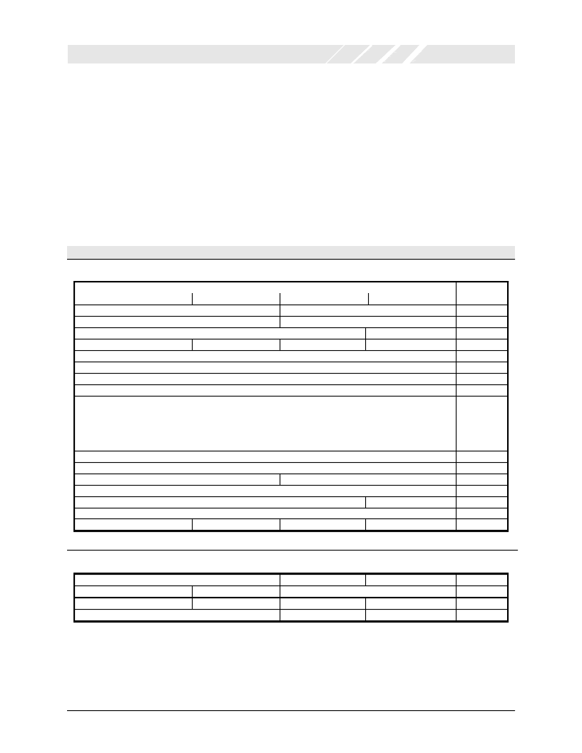
The format of the PCI configuration space, for cardbus and
pci modes, is as shown in the Table below.
In general, writes to any registers that are not implemented
are ignored, and all reads fromunimplemented registers
return 0.
Configuration Register Description
16
Offset
Address
00h
04h
08h
0Ch
10h
14h
18h
1Ch
20h
31
15
0
Device ID
Status
Vendor ID
Command
Class Code
Header Type
Revision ID
Reserved
BIST
1
Reserved
Base Address Register 0 (BAR0) – UART Function in I/O space
Base Address Register 1 (BAR 1) - UART Function in Memory space
Base Address Register 2 (BAR 2) – Local Configuration Registers in IO space
Base Address Register 3 (BAR3) – Local Configuration Registers in Memory space
Base Address Register 4 (BAR4) – Cardbus Status Registers in Memory Space
Function Event : Offset +0
Function Event Mask : Offset +4
Function Present State : Offset +8
Function Force Event : Offset +12
Reserved (Bar 5)
Cardbus CIS Pointer
SubsystemID
Reserved
Reserved
Reserved
Reserved
Reserved
24h
28h
2Ch
30h
34h
38h
3Ch
SubsystemVendor ID
Cap_Ptr
Interrupt Pin
Interrupt Line
Predefined PCI Header Region
Device Dependant PCI Region
Power Management Capabilities (PMC)
Reserved
Tuple Byte3*
…
Next Ptr
PMC Control/Status Register (PMCSR)
Tuple Byte1*
Tuple Byte (n+1)*
Cap_ID
40h
44h
48h
4Ch
Reserved
Tuple Byte 2*
Tuple Byte 0*
Tuple Byte n*
*Tuples are available for the Cardbus mode only. These fields return all 0’s for the PCI mode of the device.
Table 2: Cardbus/PCI Configuration space
相關PDF資料 |
PDF描述 |
|---|---|
| OXFW900 | IEEE1394 to ATA/ATAPI Native Bridge |
| OXFW900-TQ-A | IEEE1394 to ATA/ATAPI Native Bridge |
| OXFW911 | IEEE1394 to ATA/ATAPI Native Bridge |
| OXFW911-TQ-A | IEEE1394 to ATA/ATAPI Native Bridge |
| OZ6812 | ACPI CardBus Controller |
相關代理商/技術參數(shù) |
參數(shù)描述 |
|---|---|
| OXCB950-TQAG | 功能描述:外圍驅動器與原件 - PCI 32 bit PC Card bridge to serial prt RoHS:否 制造商:PLX Technology 工作電源電壓: 最大工作溫度: 安裝風格:SMD/SMT 封裝 / 箱體:FCBGA-1156 封裝:Tray |
| OXCB950-TQC60-A | 制造商:OXFORD 制造商全稱:OXFORD 功能描述:Integrated High Performance UART Cardbus / 3.3v PCI interface |
| OXCF950 | 制造商:OXFORD 制造商全稱:OXFORD 功能描述:low cost asynchronous 16-bit PC card or Compact Flash UART device |
| OXCF950_06 | 制造商:OXFORD 制造商全稱:OXFORD 功能描述:low cost asynchronous 16-bit PC card or Compact Flash UART device |
| OXCF950B | 制造商:PLX 制造商全稱:PLX 功能描述:16-bit PC card/CF+ bridge to serial port |
發(fā)布緊急采購,3分鐘左右您將得到回復。