- 您現(xiàn)在的位置:買賣IC網(wǎng) > PDF目錄385813 > SAA6713H (NXP Semiconductors N.V.) XGA dual input flat panel controller PDF資料下載
參數(shù)資料
| 型號: | SAA6713H |
| 廠商: | NXP Semiconductors N.V. |
| 英文描述: | XGA dual input flat panel controller |
| 中文描述: | 雙輸入的XGA液晶控制器 |
| 文件頁數(shù): | 42/103頁 |
| 文件大小: | 521K |
| 代理商: | SAA6713H |
第1頁第2頁第3頁第4頁第5頁第6頁第7頁第8頁第9頁第10頁第11頁第12頁第13頁第14頁第15頁第16頁第17頁第18頁第19頁第20頁第21頁第22頁第23頁第24頁第25頁第26頁第27頁第28頁第29頁第30頁第31頁第32頁第33頁第34頁第35頁第36頁第37頁第38頁第39頁第40頁第41頁當前第42頁第43頁第44頁第45頁第46頁第47頁第48頁第49頁第50頁第51頁第52頁第53頁第54頁第55頁第56頁第57頁第58頁第59頁第60頁第61頁第62頁第63頁第64頁第65頁第66頁第67頁第68頁第69頁第70頁第71頁第72頁第73頁第74頁第75頁第76頁第77頁第78頁第79頁第80頁第81頁第82頁第83頁第84頁第85頁第86頁第87頁第88頁第89頁第90頁第91頁第92頁第93頁第94頁第95頁第96頁第97頁第98頁第99頁第100頁第101頁第102頁第103頁
2004 Apr 05
42
Philips Semiconductors
Product specification
XGA dual input flat panel controller
SAA6713H
7.4.2
C
LOCK ACTIVATION CONTROL
The clock signals of auto-adjustment, downscaler,
upscaler and OSD module are powered-down
automatically during inactivity if programming bits
aaclk_auto, dscclk_auto, uscclk_auto and osdclk_auto
respectively in register CD_CLK_AUTO (11H) are set to
logic 1. Otherwise the clock signals are switched on and
off according to the state of bits aaclk_on, dscclk_on,
uscclk_on and osdclk_on respectively in register
CD_CLK_EN (10H).
ThegeneralconfigurationandtheOSDconfigurationclock
signal are also powered-down during inactivity unless
forced active, when cfgclk_on or osd_cfgclk_on
respectively (CD_CLK_EN, 10H) is set to logic 1.
When automatic activation is selected, each clock signal is
active during either power-on or the programmable reset
of the specific domain and whenever the concerned
module is activated.
7.4.3
PLL
PROGRAMMING
The SAA6713H contains two PLLs:
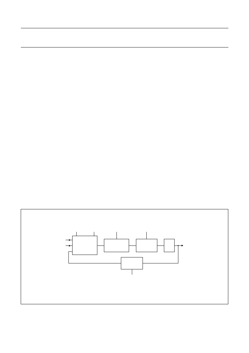
Line-locked PLL generating the sample clock from the
hsync signal (see Fig.6)
PLL running on the system clock generating the panel
clock (see Fig.7).
The PLL programming registers are mapped to register
page 0.
The PLLs are activated by pll_en and line_pll_en and the
back-end clock PLL pre-divider by pll_pre_div_en at
register CD_PLL_CTRL (20H).
Bits line_pll_vs_pol and line_pll_hs_pol define the polarity
of the vertical and horizontal sync inputs. Each bit has to
be set to logic 1 in case of positive (active HIGH) polarity
of the corresponding sync signal; otherwise to logic 0.
The outputs for the pre-divider, n-divider and m-divider
ratios are set accordingly to bits pll_pre_div, pll_m_div,
pll_n_div, line_pll_m_div and line_pll_n_div at registers
CD_PLL_P_HI to CD_LPLL_LO (21H to 26H).
The pll_n_div is a programmable divider between
100 to 4096. The relation between hsync and pll_clk is:
pll_clk = pll_n_div
×
hsync. The frequency of the oscillator
should be selected at minimum two times pll_clk.
Thepll_m_divisaprogrammabledividerbetween‘00’ = 1,
‘01’ = 2, ‘10’ = 2, ‘11’ = 4 and limits the current controlled
oscillator tuning range.
The line PLL clock is finally phase shifted as defined in
steps of 11.25 degrees by line_pll_phase at register
CD_LPLL_PHA (27H).
For the auto-adjustment phase distortion measurement
registerCD_LPLL_PDcontainsanalternativephasevalue
pd_pll_phase for the line PLL. Parameter phase_auto
enables switching between both phase values controlled
bytheauto-adjustmentifsettologic 1,ormanualselection
by phase_select.
handbook, full pagewidth
MHC215
÷
2
line PLL
clock
FREQUENCY
AND
PHASE
DETECTOR
OSCILLATOR
50 to 320 MHz
line_pll_en
m-DIVIDER
line_pll_m_div[1:0]
n-DIVIDER
line_pll_n_div[11:0]
HS_PLL
line_vs_pol
VS_PLL
line_hs_pol
Fig.6 Line PLL block diagram.
相關(guān)PDF資料 |
PDF描述 |
|---|---|
| SAA7110 | Digital Multistandard Colour Decoder(數(shù)字多標準彩色譯碼器) |
| SAA7111 | Video Input Processor VIP |
| SAA7120H | Digital video encoder |
| SAA7152 | Digital Video Comb Filter DCF |
| SAA7184 | Digital Video Encoders DENC2-M6 |
相關(guān)代理商/技術(shù)參數(shù) |
參數(shù)描述 |
|---|---|
| SAA6713H/V1 | 制造商:PHILIPS 制造商全稱:NXP Semiconductors 功能描述:XGA dual input flat panel controller |
| SAA6721 | 制造商:PHILIPS 制造商全稱:NXP Semiconductors 功能描述:SXGA RGB to TFT graphics engine |
| SAA6721E | 制造商:PHILIPS 制造商全稱:NXP Semiconductors 功能描述:SXGA RGB to TFT graphics engine |
| SAA6750 | 制造商:PHILIPS 制造商全稱:NXP Semiconductors 功能描述:Encoder for MPEG2 image recording EMPIRE |
| SAA6750H | 制造商:PHILIPS 制造商全稱:NXP Semiconductors 功能描述:Encoder for MPEG2 image recording EMPIRE |
發(fā)布緊急采購,3分鐘左右您將得到回復。