- 您現(xiàn)在的位置:買賣IC網(wǎng) > PDF目錄382377 > PCA5010H (NXP Semiconductors N.V.) Pager baseband controller PDF資料下載
參數(shù)資料
| 型號: | PCA5010H |
| 廠商: | NXP Semiconductors N.V. |
| 英文描述: | Pager baseband controller |
| 中文描述: | 傳呼機(jī)基帶控制器 |
| 文件頁數(shù): | 25/112頁 |
| 文件大小: | 627K |
| 代理商: | PCA5010H |
第1頁第2頁第3頁第4頁第5頁第6頁第7頁第8頁第9頁第10頁第11頁第12頁第13頁第14頁第15頁第16頁第17頁第18頁第19頁第20頁第21頁第22頁第23頁第24頁當(dāng)前第25頁第26頁第27頁第28頁第29頁第30頁第31頁第32頁第33頁第34頁第35頁第36頁第37頁第38頁第39頁第40頁第41頁第42頁第43頁第44頁第45頁第46頁第47頁第48頁第49頁第50頁第51頁第52頁第53頁第54頁第55頁第56頁第57頁第58頁第59頁第60頁第61頁第62頁第63頁第64頁第65頁第66頁第67頁第68頁第69頁第70頁第71頁第72頁第73頁第74頁第75頁第76頁第77頁第78頁第79頁第80頁第81頁第82頁第83頁第84頁第85頁第86頁第87頁第88頁第89頁第90頁第91頁第92頁第93頁第94頁第95頁第96頁第97頁第98頁第99頁第100頁第101頁第102頁第103頁第104頁第105頁第106頁第107頁第108頁第109頁第110頁第111頁第112頁

1998 Nov 02
25
Philips Semiconductors
Product specification
Pager baseband controller
PCA5010
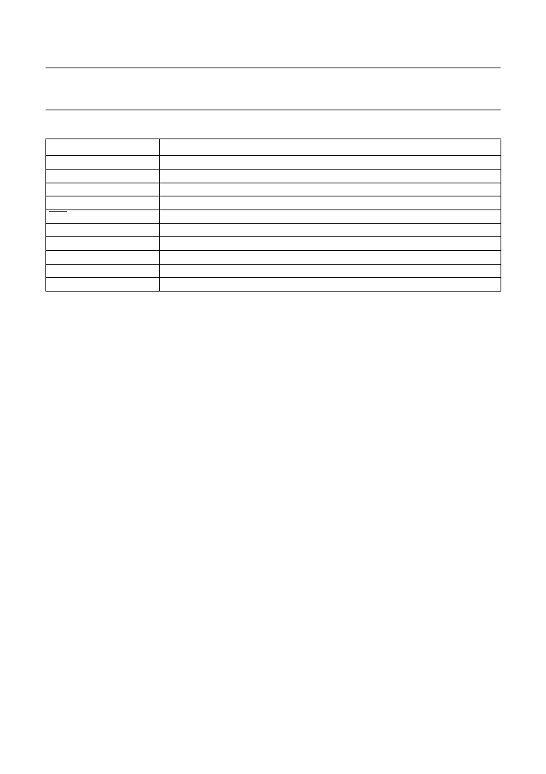
Table 15
Symbols used in Tables 12 to 14
SYMBOL
DESCRIPTION
SLA
R
W
ACK
ACK
DATA
MST
SLV
TRX
REC
7-bit slave address
read bit
write bit
acknowledgement (acknowledge bit = logic 0)
no acknowledgement (acknowledge bit = logic 1)
8-bit data byte to or from I
2
C-bus
master
slave
transmitter
receiver
6.9
Serial interface SIO0: UART
The UART interface of the PCA5010 implements a subset
of the complete standard as defined in e.g. the P80CL580.
6.9.1
D
IFFERENCES TO THE STANDARD
80C51 UART
The following deviations from the standard exist:
If [SM1 and SM0] = 10 then Mode 1 (8-bit data
transmission) is selected, with a fixed baud rate
(4800/9600 bits/s)
If [SM1 and SM0] = 01 then Mode 2 (9-bit data
transmission) is selected, with a fixed baud rate
(4800/9600 bits/s)
Modes 0 and 3 and the variable baud rate selection
using Timer 1 overflow is not available
The SM2 bit has no function
The time reference for modes 1 and 2 is taken from the
76.8 kHz oscillator, instead of the original
6.9.2
UART
MODES
This serial port is full duplex which means that it can
transmit and receive simultaneously. It is also
receive-buffered and can commence reception of a
second byte before a previously received byte has been
read from the register. However, if the first byte has not
been read by the time the reception of the second byte is
complete, the second byte will be lost. The serial port
receive and transmit registers are both accessed via the
special function register S0BUF. Writing to S0BUF loads
the transmit register and reading S0BUF accesses a
physically separate receive register.
f
-12
The serial port can operate in 2 modes:
Mode 1 10 bits are transmitted (through TXD) or received
(through RXD): a START bit (0), 8 data bits (LSB
first) and a stop bit (1). On receive, the stop bit
goes into RB8 in special function register S0CON
(see Figs 11 and 12).
Mode 2 11 bits are transmitted (through TXD) or received
(through RXD): a start bit (0), 8 data bits (LSB
first), a programmable 9th data bit and a STOP
bit (1). On transmit, the 9th data bit (TB8 in
S0CON) can be assigned the value of 0 or 1.
Or, for example, the parity bit (P, in the PSW)
could be moved into TB8. On receive, the 9th
data bit goes into RB8 in S0CON, while the STOP
bit is ignored (see Figs 11 and 13).
In both modes the baud rate can be selected to either
4800 or 9600 depending on the SMOD bit in the PCON
SFR. If SMOD = 0 the baud rate is 4800, if SMOD = 1 the
baud rate is 9600 with a 76.8 kHz quartz.
In both modes, transmission is initiated by any instruction
that uses S0BUF as a destination register. Reception is
initiated by the incoming start bit if REN = 1.
6.9.3
S
ERIAL
P
ORT
C
ONTROL
R
EGISTER
(S0CON)
The serial port control and status register is the special
function register S0CON (see Table 16). The register
contains not only the mode selection bits, but also the 9th
data bit for transmit and receive (TB8 and RB8), and the
serial port interrupt bits (TI and RI).
相關(guān)PDF資料 |
PDF描述 |
|---|---|
| PCA82C200 | STAND-ALONE CAN-CONTROLLER |
| PCA82C200P | STAND-ALONE CAN-CONTROLLER |
| PCA82C200T | STAND-ALONE CAN-CONTROLLER |
| PCA82C250 | CAN controller interface |
| PCA82C250U | CAN controller interface |
相關(guān)代理商/技術(shù)參數(shù) |
參數(shù)描述 |
|---|---|
| PCA5010H/XXX | 制造商:未知廠家 制造商全稱:未知廠家 功能描述:MICROCONTROLLER|8-BIT|8051 CPU|CMOS|QFP|48PIN|PLASTIC |
| PCA503HL320 | 制造商:ADAM-TECH 制造商全稱:Adam Technologies, Inc. 功能描述:ZIF FLEX CIRCUIT CONNECTOR |
| PCA503HU320 | 制造商:ADAM-TECH 制造商全稱:Adam Technologies, Inc. 功能描述:ZIF FLEX CIRCUIT CONNECTOR |
| PCA503V320 | 制造商:ADAM-TECH 制造商全稱:Adam Technologies, Inc. 功能描述:ZIF FLEX CIRCUIT CONNECTOR |
| PCA5075 | 制造商:未知廠家 制造商全稱:未知廠家 功能描述:Power Control/Management |
發(fā)布緊急采購,3分鐘左右您將得到回復(fù)。