- 您現(xiàn)在的位置:買賣IC網(wǎng) > PDF目錄371670 > 83C795 (SMSC Corporation) Ethernet System Controller PDF資料下載
參數(shù)資料
| 型號: | 83C795 |
| 廠商: | SMSC Corporation |
| 英文描述: | Ethernet System Controller |
| 中文描述: | 以太網(wǎng)系統(tǒng)控制器 |
| 文件頁數(shù): | 88/136頁 |
| 文件大小: | 1996K |
| 代理商: | 83C795 |
第1頁第2頁第3頁第4頁第5頁第6頁第7頁第8頁第9頁第10頁第11頁第12頁第13頁第14頁第15頁第16頁第17頁第18頁第19頁第20頁第21頁第22頁第23頁第24頁第25頁第26頁第27頁第28頁第29頁第30頁第31頁第32頁第33頁第34頁第35頁第36頁第37頁第38頁第39頁第40頁第41頁第42頁第43頁第44頁第45頁第46頁第47頁第48頁第49頁第50頁第51頁第52頁第53頁第54頁第55頁第56頁第57頁第58頁第59頁第60頁第61頁第62頁第63頁第64頁第65頁第66頁第67頁第68頁第69頁第70頁第71頁第72頁第73頁第74頁第75頁第76頁第77頁第78頁第79頁第80頁第81頁第82頁第83頁第84頁第85頁第86頁第87頁當前第88頁第89頁第90頁第91頁第92頁第93頁第94頁第95頁第96頁第97頁第98頁第99頁第100頁第101頁第102頁第103頁第104頁第105頁第106頁第107頁第108頁第109頁第110頁第111頁第112頁第113頁第114頁第115頁第116頁第117頁第118頁第119頁第120頁第121頁第122頁第123頁第124頁第125頁第126頁第127頁第128頁第129頁第130頁第131頁第132頁第133頁第134頁第135頁第136頁
7.5.6
Each TP driver transmits a short positive pulse
periodically when it is not sending data. These
pulses are received at the other end of the twisted
pair cable, signaling that the link is operating
correctly. The time between link test pulses is
compared to the expected range at the receiver to
help ignore noise pulses. If the link test fails (no
pulses or data received within a fixed time period)
then the LLED pin is set high and AUI interface is
selected. If the link is restored, the chip
automatically selects TP interface.
Link Integrity Test Function
The Link Integrity Test is also used to correct the
receiver connection’s polarity. The Link Integrity
Test signal and Start-of-Idle both have positive
polarity. The polarity correction state machine looks
at both of these to determine whether to flip receiver
polarity. Polarity correction can be disabled by a bit
in the MANCH Register (MANCH.ENAPOL).
The Link Integrity Test can be disabled by a bit in
the General Control Register (GCR.LIT). Disabling
Link Test forces the 83C795 to select the
twisted-pair interface.
7.5.7
If the internal transmit enable signal is active for
more than 46 msec, the twisted-pair transmitter will
be disabled and a collision indication is sent to the
MAC transmitter circuit. When the internal transmit
enable signal has been inactive for more than 368
msec, the internal collision indicator will become
inactive and the twisted-pair transmitter will be
re-enabled. J abber protection for the AUI port is
provided by an external MAU.
Jabber Protection
7.5.8
In twisted-pair operation, a brief internal collision
indication will be sent to the MAC transmitter after
each packet is transmitted. When an AUI port is in
use, an external MAU will provide this signal.
SQE Test (Heartbeat Test)
7.5.9
To assist in installation and management of the
network, indicator LEDs can be driven directly by
four outputs from the 83C795. These show the
result of Link Test, polarity check, transmit and
receive activity. The LED outputs can be read back
through the MANCH register to support network
management functions.
Status Indications
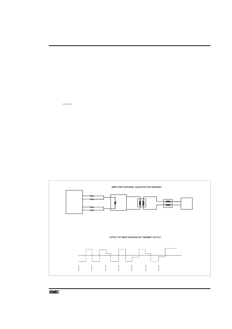
83C795
Elliptic
10Filter
Jack
TPX2+
TPX1+
R
2
R
6
R
6
R
2
TPX1-
TPX2-
R31 || R32 = 50 Ohm = R33 || R34
Ratio of R31 to R32 determines how much smaller the
second half of the pulse is than the first half
1
1
0
0
1
0
1
PTPX1
TPX2
+
+
+
+
+
-
-
-
-
-
-
-
+
+
+
-
-
+
-
+
+
+
-
-
+
+
FIGURE 7-3. SIMPLIFIED TRANSMIT CIRCUITRY
LAN CONTROLLER OVERVIEW
83C795
75
相關(guān)PDF資料 |
PDF描述 |
|---|---|
| 84063 | The Constituents of Semiconductor Components |
| 8406601QA | CMOS Programmable Peripheral Interface |
| 8406601XA | CMOS Programmable Peripheral Interface |
| 8406602XA | CMOS Programmable Peripheral Interface |
| 8406602QA | CMOS Programmable Peripheral Interface |
相關(guān)代理商/技術(shù)參數(shù) |
參數(shù)描述 |
|---|---|
| 83C800-009 | 制造商:DRS 功能描述: |
| 83C825EQFP | 制造商:SMSC 功能描述: |
| 83C845 | 制造商:PHILIPS 制造商全稱:NXP Semiconductors 功能描述:Microcontrollers for TV and video MTV |
| 83C851 | 制造商:PHILIPS 制造商全稱:NXP Semiconductors 功能描述:CMOS single-chip 8-bit microcontroller with on-chip EEPROM |
| 83C852DIE | 制造商:未知廠家 制造商全稱:未知廠家 功能描述:8-Bit Microcontroller |
發(fā)布緊急采購,3分鐘左右您將得到回復(fù)。