- 您現(xiàn)在的位置:買賣IC網(wǎng) > PDF目錄382377 > PCA5007H (NXP Semiconductors N.V.) Pager baseband controller PDF資料下載
參數(shù)資料
| 型號(hào): | PCA5007H |
| 廠商: | NXP Semiconductors N.V. |
| 英文描述: | Pager baseband controller |
| 中文描述: | 傳呼機(jī)基帶控制器 |
| 文件頁數(shù): | 82/112頁 |
| 文件大小: | 604K |
| 代理商: | PCA5007H |
第1頁第2頁第3頁第4頁第5頁第6頁第7頁第8頁第9頁第10頁第11頁第12頁第13頁第14頁第15頁第16頁第17頁第18頁第19頁第20頁第21頁第22頁第23頁第24頁第25頁第26頁第27頁第28頁第29頁第30頁第31頁第32頁第33頁第34頁第35頁第36頁第37頁第38頁第39頁第40頁第41頁第42頁第43頁第44頁第45頁第46頁第47頁第48頁第49頁第50頁第51頁第52頁第53頁第54頁第55頁第56頁第57頁第58頁第59頁第60頁第61頁第62頁第63頁第64頁第65頁第66頁第67頁第68頁第69頁第70頁第71頁第72頁第73頁第74頁第75頁第76頁第77頁第78頁第79頁第80頁第81頁當(dāng)前第82頁第83頁第84頁第85頁第86頁第87頁第88頁第89頁第90頁第91頁第92頁第93頁第94頁第95頁第96頁第97頁第98頁第99頁第100頁第101頁第102頁第103頁第104頁第105頁第106頁第107頁第108頁第109頁第110頁第111頁第112頁

1998 Oct 07
82
Philips Semiconductors
Product specification
Pager baseband controller
PCA5007
Notes
1.
DC/DC converter configured with inductor of L = 470
μ
H, SRL = 5
, input capacitance of C
i
= 4.7
μ
F, ESR = 0.5
,
V
DD
output capacitor C
o
= 4.7
μ
F, ESR = 0.5
, R
BAT
< 1
.
This parameter is not tested during production; it is guaranteed by design.
This parameter depends on external components.
At high load or low battery voltage the inductor charge time can be extended to a full XTL1 period, while the minimum
inductor discharge time remains an
1
2
t
XTL1
period.
The execution time is strongly dependant on command type and addressing mode (see Table 60).
2.
3.
4.
5.
ZIF (I and Q) demodulator
f
offset
S/N
t
(ENA-AVG)
t
ENB
offset from 0 frequency
minimum signal strength
ENA to valid AVG value
ENB to valid demodulator
output
ENB to correct recovered
clock
changing baud rate to
correct recovered clock
note 2
3% bit error rate; note 2
3 kHz offset; note 2
24 samples per symbol;
note 2
note 2
6
95
100
1
kHz
dB(m)
ms
symbol
duration
t
ENC
12/12 positive/negative
transitions of data
2/2 positive/negative
transitions of data
t
BR
note 2
All outputs
t
r,f
rise and fall times for outputs C
L
= 20 pF
15
ns
Open-drain pins SDA and SCL (P1.7 and P1.6)
t
noise
V/
t
noise suppression filter time
slope for the falling edge
60
50
ns
ns/V
R
L
= 20 k
; C
L
= 50 pF;
V
DD
= 2.2 V
R
L
= 20 k
; C
L
= 50 pF
V
DD
= 2.2 V; R
L
= 20 k
;
C
L
= 50 pF
δ
I/
δ
t
I
o(sink)(swL)
slope for both edges
dynamic output sink current
during switching low (Miller
compensated)
250
2
μ
A/ns
mA
OTP programming characteristics
t
SU;VPP
t
W(prog)
t
W(prog)(sec)
t
W(prog)(rec)
V
PP
set-up time
program pulse width
program pulse security bits
program pulse recover time
10
100
200
1
μ
s
μ
s
μ
s
μ
s
AFC-DAC
t
start(DAC)
start-up time disabled DAC
to stable output for code
111111
power supply ripple rejection
(V
DD
-> DAC)
slew time for analog output
from 10 to 90% for a voltage
step of 1 V
note 2
50
100
μ
s
PSRR
0
dB
t
slew
code 010000 <-> 110000
2.5
μ
s
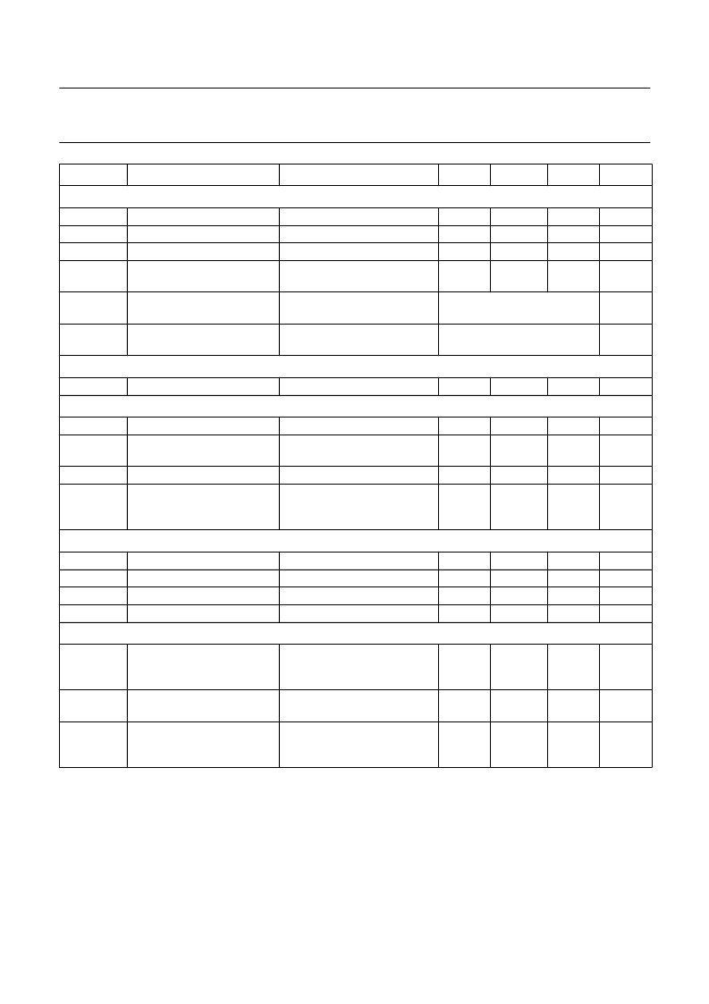
SYMBOL
PARAMETER
CONDITIONS
MIN.
TYP
MAX.
UNIT
相關(guān)PDF資料 |
PDF描述 |
|---|---|
| PCA5010 | Pager baseband controller |
| PCA5010H | Pager baseband controller |
| PCA82C200 | STAND-ALONE CAN-CONTROLLER |
| PCA82C200P | STAND-ALONE CAN-CONTROLLER |
| PCA82C200T | STAND-ALONE CAN-CONTROLLER |
相關(guān)代理商/技術(shù)參數(shù) |
參數(shù)描述 |
|---|---|
| PCA5007H/XXX | 制造商:未知廠家 制造商全稱:未知廠家 功能描述:8-Bit Microcontroller |
| PCA5010 | 制造商:PHILIPS 制造商全稱:NXP Semiconductors 功能描述:Pager baseband controller |
| PCA5010H | 制造商:PHILIPS 制造商全稱:NXP Semiconductors 功能描述:Pager baseband controller |
| PCA5010H/XXX | 制造商:未知廠家 制造商全稱:未知廠家 功能描述:MICROCONTROLLER|8-BIT|8051 CPU|CMOS|QFP|48PIN|PLASTIC |
| PCA503HL320 | 制造商:ADAM-TECH 制造商全稱:Adam Technologies, Inc. 功能描述:ZIF FLEX CIRCUIT CONNECTOR |
發(fā)布緊急采購,3分鐘左右您將得到回復(fù)。