- 您現(xiàn)在的位置:買賣IC網(wǎng) > PDF目錄372115 > SAA7381 (NXP SEMICONDUCTORS) ATAPI CD-R block decoder PDF資料下載
參數(shù)資料
| 型號: | SAA7381 |
| 廠商: | NXP SEMICONDUCTORS |
| 元件分類: | 消費家電 |
| 英文描述: | ATAPI CD-R block decoder |
| 中文描述: | SPECIALTY CONSUMER CIRCUIT, PQFP144 |
| 文件頁數(shù): | 54/108頁 |
| 文件大?。?/td> | 380K |
| 代理商: | SAA7381 |
第1頁第2頁第3頁第4頁第5頁第6頁第7頁第8頁第9頁第10頁第11頁第12頁第13頁第14頁第15頁第16頁第17頁第18頁第19頁第20頁第21頁第22頁第23頁第24頁第25頁第26頁第27頁第28頁第29頁第30頁第31頁第32頁第33頁第34頁第35頁第36頁第37頁第38頁第39頁第40頁第41頁第42頁第43頁第44頁第45頁第46頁第47頁第48頁第49頁第50頁第51頁第52頁第53頁當前第54頁第55頁第56頁第57頁第58頁第59頁第60頁第61頁第62頁第63頁第64頁第65頁第66頁第67頁第68頁第69頁第70頁第71頁第72頁第73頁第74頁第75頁第76頁第77頁第78頁第79頁第80頁第81頁第82頁第83頁第84頁第85頁第86頁第87頁第88頁第89頁第90頁第91頁第92頁第93頁第94頁第95頁第96頁第97頁第98頁第99頁第100頁第101頁第102頁第103頁第104頁第105頁第106頁第107頁第108頁
1997 Aug 12
54
Philips Semiconductors
Objective specification
ATAPI CD-R block decoder
SAA7381
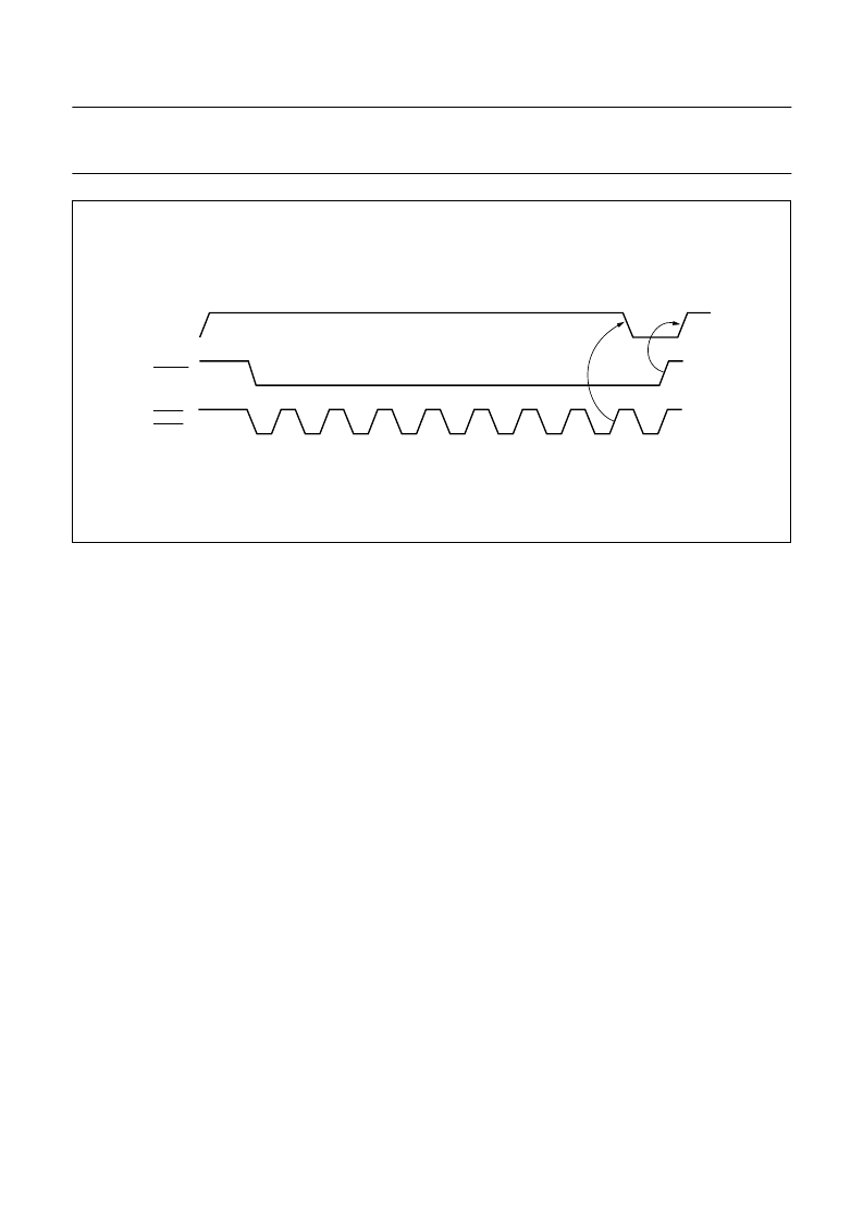
Fig.6 Burst DMA mode using multiplexed bus configuration.
handbook, full pagewidth
MGK515
DMACK
DBRD/
DBWR
7.6
Microcontroller interface
This section provides a brief introduction to the software
and hardware environment expected in a system using the
SAA7381 device. Because all of the SAA7381 registers
are randomly accessible, the processor controlling the
SAA7381 is able to use interrupts.
7.6.1
K
ERNEL BASED FIRMWARE
It is recommended that the sub-CPU runs a multi-tasking
kernel to properly support the multiple ‘threads’ of
operation that are required of it in use. Therefore the
memory mapper specified in this document has the
concept of having 2 pages of memory for data. Then one
page of data space can be switched in to the memory map
for each thread as needed, while still keeping a fixed part
of the memory map for the interrupt service routines and
other fixed housekeeping code and data.
7.6.2
16-
BIT REGISTERS AUTOMATIC READ AND WRITE
All of the 16-bit registers provided in the SAA7381, are
used by writing the Most Significant Bit (MSB) first. These
registers are located in the address range FF20H to
FF6FH together with some 8-bit registers. To facilitate
‘snapshot’ reading or writing of the 16-bit register an 8-bit
holding register is provided to store the ‘spare’ byte of
data.
This is implemented in such a way that a 16-bit read
consists of a sample of the value of the register at the
instant that the high byte was read from that register.
The low byte is kept in a holding register and presented to
the sub-CPU when the low byte is requested. Even if the
sub-CPU is interrupted (and the holding register is then
stacked and replaced during the service routine) the 16-bit
read will be the value of the register at a single instance in
time.
Similarly for writing, the high byte is held in the holding
register to be written later to the 16-bit register at the same
time as the low byte is written to the SAA7381. Again the
holding register must be saved during an Interrupt Service
Routine (ISR) if the ISR itself is likely to cause any 16-bit
reads or writes to take place. It should be noted that any
ISR, which requires access to a 16-bit or 8-bit register in
the address range FF20H to FF6FH, will overwrite the
holding register and therefore its contents must be stacked
before the interrupt is serviced. Furthermore, there is only
one holding register that may be accessed both for reading
and writing. In this way the interrupt routine can easily save
data that was stored in the holding register before it was
written.
A single location (TEMP_DATA, register FF6FH) is used
as the location to read the value of the holding register,
regardless of which address was used in the original read
or write process. The IRS stacking process of the holding
register is illustrated in Fig.8.
相關(guān)PDF資料 |
PDF描述 |
|---|---|
| SAA7382GP | Error correction and host interface IC for CD-ROM ELM |
| SAA7382 | Error correction and host interface IC for CD-ROM ELM |
| SAA7390 | High performance Compact Disc-Recordable CD-R controller |
| SAA7390GP | High performance Compact Disc-Recordable CD-R controller |
| SAA7501WP | ARD/ZDF NR.3R1 DIGITAL DECODER|LDCC|68PIN|PLASTIC |
相關(guān)代理商/技術(shù)參數(shù) |
參數(shù)描述 |
|---|---|
| SAA7382 | 制造商:PHILIPS 制造商全稱:NXP Semiconductors 功能描述:Error correction and host interface IC for CD-ROM ELM |
| SAA7382GP | 制造商:PHILIPS 制造商全稱:NXP Semiconductors 功能描述:Error correction and host interface IC for CD-ROM ELM |
| SAA7384 | 制造商:PHILIPS 制造商全稱:NXP Semiconductors 功能描述:Terrestrial digital sound decoder for conventional intercarrier PLL-IF systems |
| SAA7385 | 制造商:PHILIPS 制造商全稱:NXP Semiconductors 功能描述:Error correction and host interface IC for CD-ROM SEQUOIA |
| SAA7385GP | 制造商:PHILIPS 制造商全稱:NXP Semiconductors 功能描述:Error correction and host interface IC for CD-ROM SEQUOIA |
發(fā)布緊急采購,3分鐘左右您將得到回復。