- 您現(xiàn)在的位置:買賣IC網(wǎng) > PDF目錄98068 > S1C6P466D0A0A00 MICROCONTROLLER, UUC140 PDF資料下載
參數(shù)資料
| 型號: | S1C6P466D0A0A00 |
| 元件分類: | 微控制器/微處理器 |
| 英文描述: | MICROCONTROLLER, UUC140 |
| 封裝: | DIE-140 |
| 文件頁數(shù): | 21/174頁 |
| 文件大小: | 1582K |
| 代理商: | S1C6P466D0A0A00 |
第1頁第2頁第3頁第4頁第5頁第6頁第7頁第8頁第9頁第10頁第11頁第12頁第13頁第14頁第15頁第16頁第17頁第18頁第19頁第20頁當(dāng)前第21頁第22頁第23頁第24頁第25頁第26頁第27頁第28頁第29頁第30頁第31頁第32頁第33頁第34頁第35頁第36頁第37頁第38頁第39頁第40頁第41頁第42頁第43頁第44頁第45頁第46頁第47頁第48頁第49頁第50頁第51頁第52頁第53頁第54頁第55頁第56頁第57頁第58頁第59頁第60頁第61頁第62頁第63頁第64頁第65頁第66頁第67頁第68頁第69頁第70頁第71頁第72頁第73頁第74頁第75頁第76頁第77頁第78頁第79頁第80頁第81頁第82頁第83頁第84頁第85頁第86頁第87頁第88頁第89頁第90頁第91頁第92頁第93頁第94頁第95頁第96頁第97頁第98頁第99頁第100頁第101頁第102頁第103頁第104頁第105頁第106頁第107頁第108頁第109頁第110頁第111頁第112頁第113頁第114頁第115頁第116頁第117頁第118頁第119頁第120頁第121頁第122頁第123頁第124頁第125頁第126頁第127頁第128頁第129頁第130頁第131頁第132頁第133頁第134頁第135頁第136頁第137頁第138頁第139頁第140頁第141頁第142頁第143頁第144頁第145頁第146頁第147頁第148頁第149頁第150頁第151頁第152頁第153頁第154頁第155頁第156頁第157頁第158頁第159頁第160頁第161頁第162頁第163頁第164頁第165頁第166頁第167頁第168頁第169頁第170頁第171頁第172頁第173頁第174頁
S1C6P466 TECHNICAL MANUAL
EPSON
107
CHAPTER 7: SUMMARY OF NOTES
Programmable timer
(1) When reading counter data, be sure to read the low-order 4 bits (PTD00–PTD03, PTD10–PTD13) first.
Furthermore, the high-order 4 bits (PTD04–PTD07, PTD14–PTD17) should be read within 0.73 msec
(when fOSC1 is 32.768 kHz) of reading the low-order 4 bits (PTD00–PTD03, PTD10–PTD13).
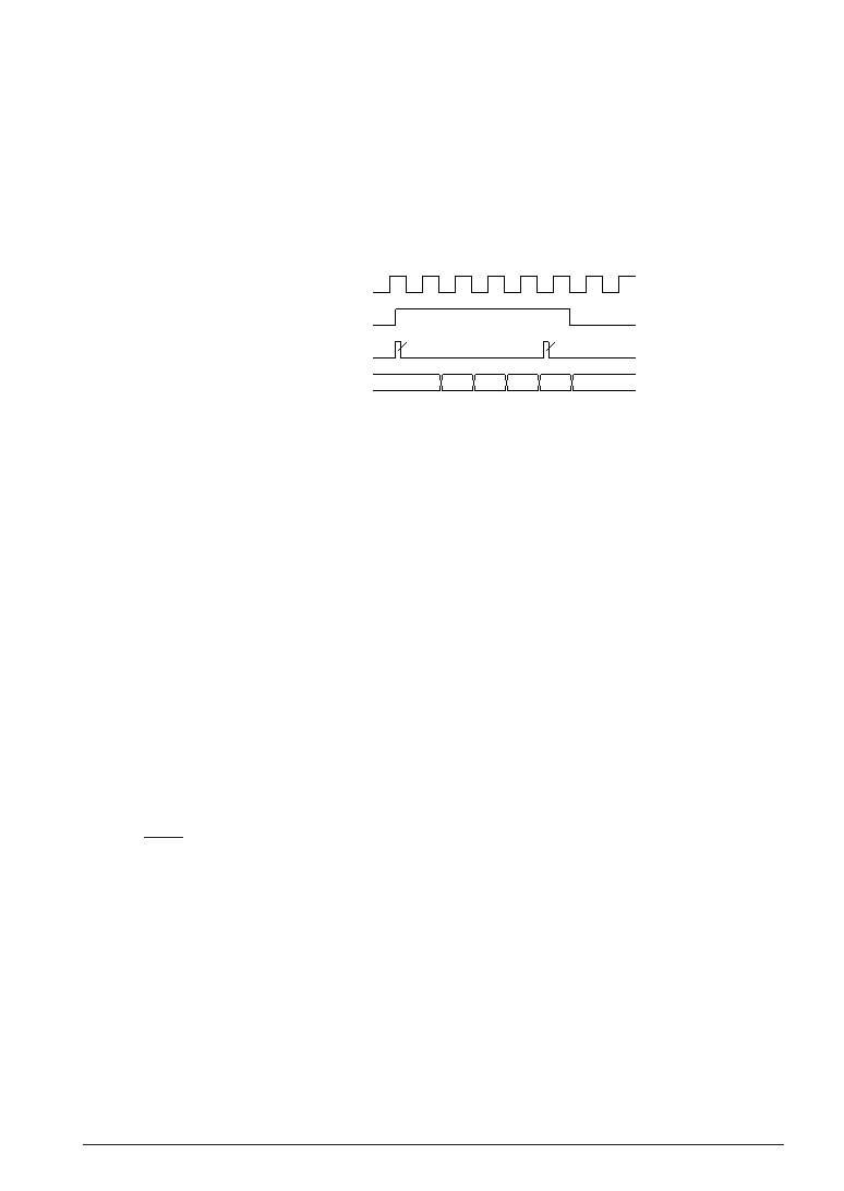
(2) The programmable timer actually enters RUN/STOP status in synchronization with the falling edge of
the input clock after writing to the PTRUN0/PTRUN1 register. Consequently, when "0" is written to the
PTRUN0/PTRUN1 register, the timer enters STOP status at the point where the counter is decremented
(-1). The PTRUN0/PTRUN1 register maintains "1" for reading until the timer actually stops.
Figure 7.2.1 shows the timing chart for the RUN/STOP control.
PTRUN0/PTRUN1 (WR)
PTD0X/PTD1X
42H
41H 40H 3FH 3EH
3DH
PTRUN0/PTRUN1 (RD)
Input clock
"1" (RUN)
writing
"0" (STOP)
writing
Fig. 7.2.1 Timing chart for RUN/STOP control
It is the same even in the event counter mode. Therefore, be aware that the counter does not enter
RUN/STOP status if a clock is not input after setting the RUN/STOP control register (PTRUN0).
(3) Since the TOUT signal is generated asynchronously from the PTOUT register, a hazard within 1/2
cycle is generated when the signal is turned ON and OFF by setting the register.
(4) When the OSC3 oscillation clock is selected for the clock source, it is necessary to turn the OSC3
oscillation ON, prior to using the programmable timer. However the OSC3 oscillation circuit requires
a time at least 5 msec from turning the circuit ON until the oscillation stabilizes. Therefore, allow an
adequate interval from turning the OSC3 oscillation circuit ON to starting the programmable timer.
Refer to Section 4.3, "Oscillation Circuit", for the control and notes of the OSC3 oscillation circuit.
At initial reset, the OSC3 oscillation circuit is set in the OFF state.
Serial interface
(1) Perform data writing/reading to the data registers SD0–SD7 only while the serial interface is halted
(i.e., the synchronous clock is neither being input or output).
(2) As a trigger condition, it is required that data writing or reading on data registers SD0–SD7 be
performed prior to writing "1" to SCTRG. (The internal circuit of the serial interface is initiated
through data writing/reading on data registers SD0–SD7.) In addition, be sure to enable the serial
interface with the ESIF register before the trigger.
Supply trigger only once every time the serial interface is placed in the RUN state. Refrain from
performing trigger input multiple times, as leads to malfunctioning. Moreover, when the synchronous
clock SCLK is external clock, start to input the external clock after the trigger.
(3) Setting of the input/output permutation (MSB first/LSB first) with the SDP register should be done
before setting data to SD0–SD7.
(4) Be aware that the maximum clock frequency for the serial interface is limited to 1 MHz when OSC3 is
used as the clock source of the programmable timer or in the slave mode.
Sound generator
(1) Since it generates a BZ signal that is out of synchronization with the BZE register, hazards may at
times be produced when the signal goes ON/OFF due to the setting of the BZE register.
(2) The one-shot output is only valid when the normal buzzer output is OFF (BZE = "0") and will be
invalid when the normal buzzer output is ON (BZE = "1").
相關(guān)PDF資料 |
PDF描述 |
|---|---|
| S1C6S2L7D | 4-BIT, MROM, 0.032 MHz, MICROCONTROLLER, UUC58 |
| S1C6S2A7F | 4-BIT, MROM, 0.08 MHz, MICROCONTROLLER, PQFP60 |
| S1C6S2B7F | 4-BIT, MROM, 0.08 MHz, MICROCONTROLLER, PQFP60 |
| S1C6S2N7D | 4-BIT, MROM, 0.08 MHz, MICROCONTROLLER, UUC58 |
| S1C6S2N7F0A0100 | MICROCONTROLLER, PQFP60 |
相關(guān)代理商/技術(shù)參數(shù) |
參數(shù)描述 |
|---|---|
| S1C-6-S | 制造商:GRIPCO 功能描述: |
| S1C7309X | 制造商:SAMSUNG 制造商全稱:Samsung semiconductor 功能描述:B/W CCD PROCESSOR |
| S1C7309X01 | 制造商:SAMSUNG 制造商全稱:Samsung semiconductor 功能描述:B/W CCD PROCESSOR |
| S1C88349 | 制造商:EPSON 制造商全稱:EPSON 功能描述:8-bit Single Chip Microcomputer |
| S1C88649 | 制造商:EPSON 制造商全稱:EPSON 功能描述:8-bit Single Chip Microcomputer |
發(fā)布緊急采購,3分鐘左右您將得到回復(fù)。