- 您現(xiàn)在的位置:買賣IC網(wǎng) > PDF目錄98068 > S1C60L16F0A0100 4-BIT, MROM, 0.032768 MHz, MICROCONTROLLER, PQFP80 PDF資料下載
參數(shù)資料
| 型號(hào): | S1C60L16F0A0100 |
| 元件分類: | 微控制器/微處理器 |
| 英文描述: | 4-BIT, MROM, 0.032768 MHz, MICROCONTROLLER, PQFP80 |
| 封裝: | PLASTIC, QFP14-80 |
| 文件頁(yè)數(shù): | 80/105頁(yè) |
| 文件大?。?/td> | 841K |
| 代理商: | S1C60L16F0A0100 |
第1頁(yè)第2頁(yè)第3頁(yè)第4頁(yè)第5頁(yè)第6頁(yè)第7頁(yè)第8頁(yè)第9頁(yè)第10頁(yè)第11頁(yè)第12頁(yè)第13頁(yè)第14頁(yè)第15頁(yè)第16頁(yè)第17頁(yè)第18頁(yè)第19頁(yè)第20頁(yè)第21頁(yè)第22頁(yè)第23頁(yè)第24頁(yè)第25頁(yè)第26頁(yè)第27頁(yè)第28頁(yè)第29頁(yè)第30頁(yè)第31頁(yè)第32頁(yè)第33頁(yè)第34頁(yè)第35頁(yè)第36頁(yè)第37頁(yè)第38頁(yè)第39頁(yè)第40頁(yè)第41頁(yè)第42頁(yè)第43頁(yè)第44頁(yè)第45頁(yè)第46頁(yè)第47頁(yè)第48頁(yè)第49頁(yè)第50頁(yè)第51頁(yè)第52頁(yè)第53頁(yè)第54頁(yè)第55頁(yè)第56頁(yè)第57頁(yè)第58頁(yè)第59頁(yè)第60頁(yè)第61頁(yè)第62頁(yè)第63頁(yè)第64頁(yè)第65頁(yè)第66頁(yè)第67頁(yè)第68頁(yè)第69頁(yè)第70頁(yè)第71頁(yè)第72頁(yè)第73頁(yè)第74頁(yè)第75頁(yè)第76頁(yè)第77頁(yè)第78頁(yè)第79頁(yè)當(dāng)前第80頁(yè)第81頁(yè)第82頁(yè)第83頁(yè)第84頁(yè)第85頁(yè)第86頁(yè)第87頁(yè)第88頁(yè)第89頁(yè)第90頁(yè)第91頁(yè)第92頁(yè)第93頁(yè)第94頁(yè)第95頁(yè)第96頁(yè)第97頁(yè)第98頁(yè)第99頁(yè)第100頁(yè)第101頁(yè)第102頁(yè)第103頁(yè)第104頁(yè)第105頁(yè)
66
EPSON
S1C60N16 TECHNICAL MANUAL
CHAPTER 4: PERIPHERAL CIRCUITS AND OPERATION (SVD Circuit)
4.14 Supply Voltage Detection (SVD) Circuit
4.14.1 Configuration of SVD circuit
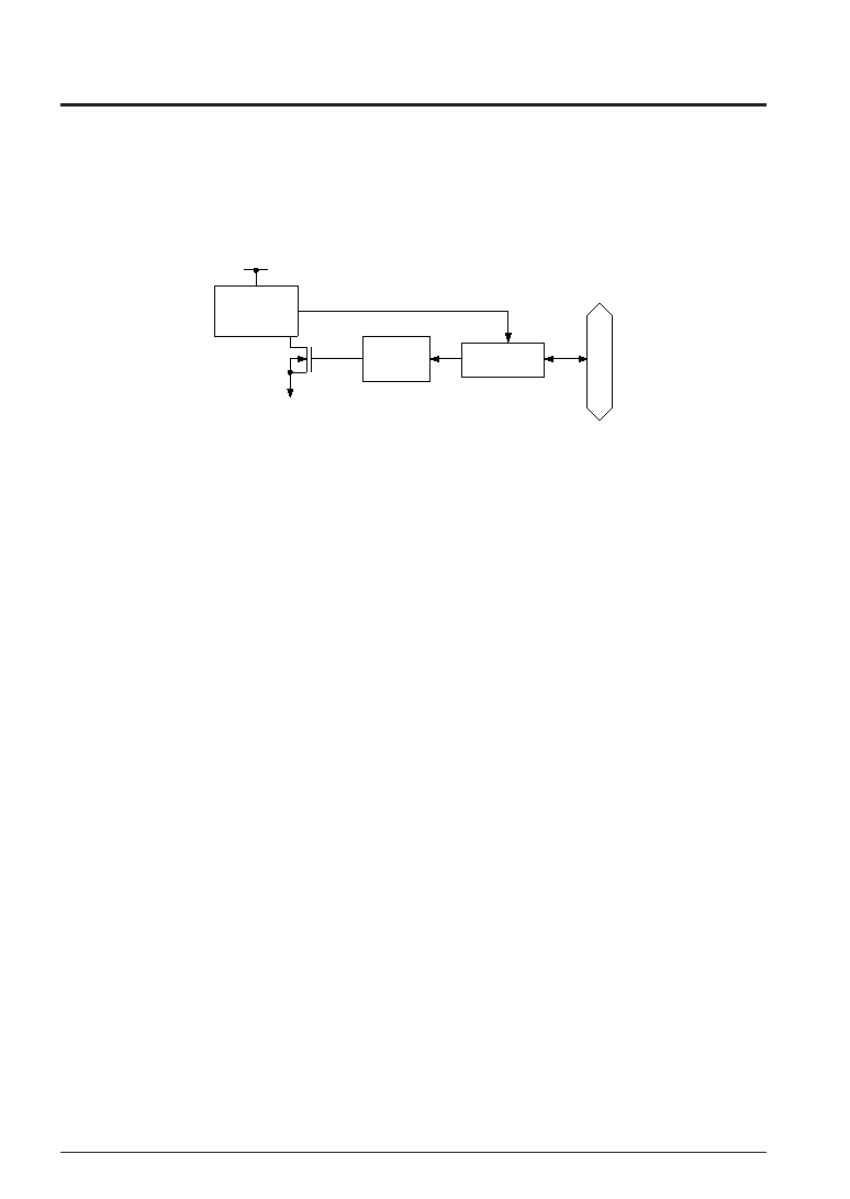
The S1C60N16 Series has a built-in supply voltage detection (SVD) circuit, so that the software can find
when the source voltage lowers. The configuration of the SVD circuit is shown in Figure 4.14.1.1.
Turning the SVD operation ON/OFF is controlled through the software (SVDON).
Because the power current consumption of the IC increases when the SVD operation is turned ON, set the
SVD operation to OFF unless otherwise necessary.
VSS
SVD circuit
Data
bus
SVD
sampling
control
VDD
Address 2FFH
SVDON/
SVDDT
Detection output
Fig. 4.14.1.1 Configuration of SVD circuit
In the S1C60N16 Series, the evaluation voltage is set as follows:
S1C60N16: 2.2 V
S1C60L16: 1.2 V
S1C60A16: 2.2 V
See Chapter 7, "Electrical Characteristics", for the evaluation voltage accuracy.
4.14.2 Detection timing of SVD circuit
This section explains the timing for when the SVD circuit writes the result of the supply voltage detection
to the SVD latch.
Turning the SVD operation ON/OFF is controlled through the software (SVDON).
The result of the source voltage detection is written to the SVD latch by the SVD circuit, and this data can
be read out by the software to find the status of the source voltage.
When SVDON is set to "1", SVD detection is executed. As soon as SVDON is reset to "0" the detection
result is loaded to the SVD latch. To obtain a stable SVD detection result, the SVD circuit must be set to
ON with at least 100 sec. Hence, to obtain the SVD detection result, follow the programming sequence
below.
1. Set SVDON to "1"
2. Maintain at 100 sec minimum
3. Set SVDON to "0"
4. Read out SVDDT
However, when a crystal oscillation clock (fOSC1) is selected for the CPU system clock in the S1C60N16,
S1C60L16, and S1C60A16, the instruction cycles are long enough, so that there is no need for concern
about maintaining 100 sec for the SVDON = "1" with the software.
相關(guān)PDF資料 |
PDF描述 |
|---|---|
| S1C60N01F | 4-BIT, MROM, 0.08 MHz, MICROCONTROLLER, PQFP48 |
| S1C60N02D | 4-BIT, MROM, 0.08 MHz, MICROCONTROLLER, UUC52 |
| S1C60L02 | 4-BIT, MROM, 0.08 MHz, MICROCONTROLLER, PQFP60 |
| S1C60N04D | 4-BIT, MROM, 2 MHz, MICROCONTROLLER, UUC48 |
| S1C60N08D | 4-BIT, MROM, 0.032768 MHz, MICROCONTROLLER, UUC96 |
相關(guān)代理商/技術(shù)參數(shù) |
參數(shù)描述 |
|---|---|
| S1C60N05 | 制造商:EPSON 制造商全稱:EPSON 功能描述:4-bit Single Chip Microcomputer |
| S1C60N08 | 制造商:EPSON 制造商全稱:EPSON 功能描述:4-bit Single Chip Microcomputer |
| S1C60N16 | 制造商:EPSON 制造商全稱:EPSON 功能描述:4-bit Single Chip Microcomputer |
| S1C60R08 | 制造商:EPSON 制造商全稱:EPSON 功能描述:4-bit Single Chip Microcomputer |
| S1C63004 | 制造商:EPSON 制造商全稱:EPSON 功能描述:CMOS 4-bit Single Chip Microcontroller |
發(fā)布緊急采購(gòu),3分鐘左右您將得到回復(fù)。