- 您現(xiàn)在的位置:買賣IC網(wǎng) > PDF目錄382385 > PCT1789N PCT303DL PDF資料下載
參數(shù)資料
| 型號(hào): | PCT1789N |
| 英文描述: | PCT303DL |
| 中文描述: | PCT303DL |
| 文件頁(yè)數(shù): | 26/40頁(yè) |
| 文件大小: | 632K |
| 代理商: | PCT1789N |
第1頁(yè)第2頁(yè)第3頁(yè)第4頁(yè)第5頁(yè)第6頁(yè)第7頁(yè)第8頁(yè)第9頁(yè)第10頁(yè)第11頁(yè)第12頁(yè)第13頁(yè)第14頁(yè)第15頁(yè)第16頁(yè)第17頁(yè)第18頁(yè)第19頁(yè)第20頁(yè)第21頁(yè)第22頁(yè)第23頁(yè)第24頁(yè)第25頁(yè)當(dāng)前第26頁(yè)第27頁(yè)第28頁(yè)第29頁(yè)第30頁(yè)第31頁(yè)第32頁(yè)第33頁(yè)第34頁(yè)第35頁(yè)第36頁(yè)第37頁(yè)第38頁(yè)第39頁(yè)第40頁(yè)
PC-TEL, Inc.
48
1789N0DOCDAT01A-0399
PCT1789N DATA SHEET
303DL C
ONTROL
R
EGISTERS
!
PRELIMINARY
PRELIMINARY
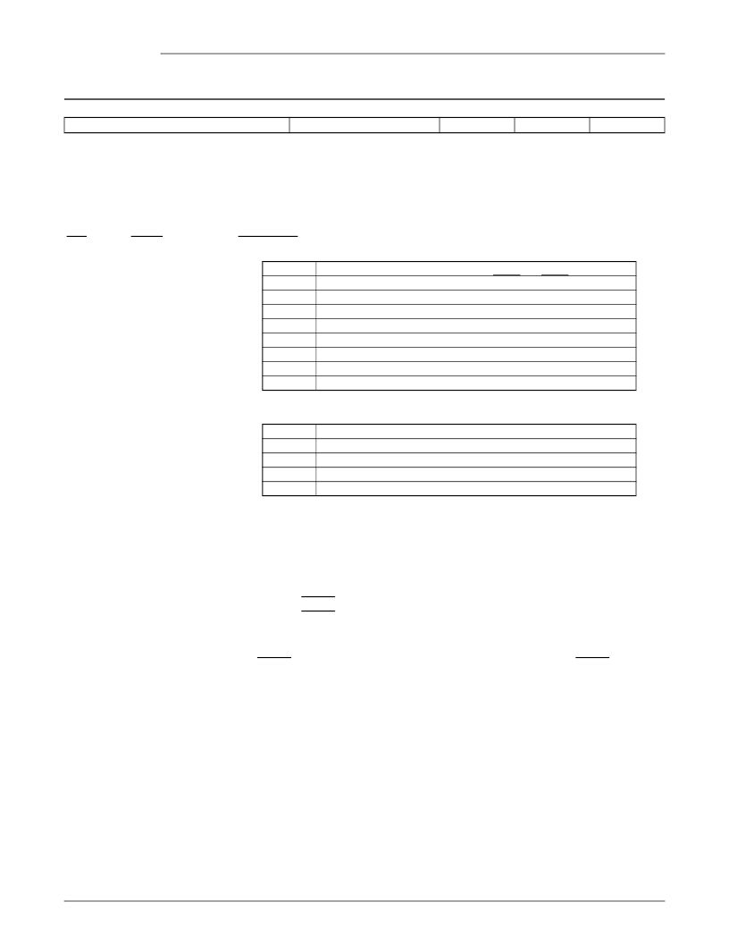
Daisy-Chain Control
(Register 14, R/W)
Reset settings: 02h (serial mode 0,1)
Reset settings: 3Fh (serial mode 2)
Bit Definitions:
NSLV[2:0]
6
SSEL[1:0]
FSD
2
RPOL
1
DCE
0
7
5
4
3
Bits
Name
NSLV[2:0]
Description
Number of slave devices.
7:5
4:3
SSEL[1:0]
Slave device select.
2
FSD
Delayed frame sync control.
1 = Sets the number of SCLK periods between frame syncs to 16.
0 = Sets the number of SCLK periods between frame syncs to 32.
This bit MUST be set when 303DL devices are used as slaves. For the master
303DL, only serial mode 1 is allowed in this case.
Ring detect polarity.
1 = The FC/RGDT pin (operating as ring detect) is active-high.
0 = The FC/RGDT pin (operating as ring detect) is active-low.
Daisy-chain enable.
1 = Enables the 303DL to operate with slave devices on the same serial bus. The
FC/RGDT signal (pin 7) becomes the ring detect output and the RGDT/FSD sig-
nal (pin 15) becomes the delayed frame sync signal. Note that ALL other bits in
this register are ignored if DCE = 0.
1
RPOL
0
DCE
NSLV[2:0]
000
001
010
011
100
101
110
111
Description
0 slave devices. Simply redefines the FC/RGDT and RGDT/FSD pins.
1 slave device.
2 slave devices.
3 slave devices.
4 slave devices. For four or more slave devices, the FSD bit MUST be set.
5 slave devices.
6 slave devices.
7 slave devices.
SSEL[1:0]
00
01
10
11
Description
16-bit SDO receive data.
Reserved.
15-bit SDO receive data. LSB = 1 for the 303DL device.
15-bit SDO receive data. LSB = 0 for the 303DL device.
相關(guān)PDF資料 |
PDF描述 |
|---|---|
| PCV250TWG5 | |
| PCV250TWLY5 | |
| PCV250TWO5 | |
| PCV250TWPG5 | |
| PCV250TWR5 | |
相關(guān)代理商/技術(shù)參數(shù) |
參數(shù)描述 |
|---|---|
| PCT-178F-Q | 制造商:Panduit Corp 功能描述: |
| PCT-179F-Q | 制造商:Panduit Corp 功能描述:Call vendor for pricing |
| PCT-18 | 制造商:Stancor 功能描述: |
| PCT-182F-Q | 制造商:Panduit Corp 功能描述: |
| PCT-1861 | 制造商:MICRO-ELECTRONICS 制造商全稱:Micro Electronics 功能描述:MODEM TRANSFORMER |
發(fā)布緊急采購(gòu),3分鐘左右您將得到回復(fù)。