- 您現(xiàn)在的位置:買(mǎi)賣(mài)IC網(wǎng) > Datasheet目錄45 > NCT7491RQR2G (ON Semiconductor)IC REMOTE THERMAL MONITOR 24QSOP Datasheet資料下載
參數(shù)資料
| 型號(hào): | NCT7491RQR2G |
| 廠商: | ON Semiconductor |
| 文件頁(yè)數(shù): | 61/80頁(yè) |
| 文件大小: | 844K |
| 描述: | IC REMOTE THERMAL MONITOR 24QSOP |
| 標(biāo)準(zhǔn)包裝: | 2,500 |
| 系列: | * |
第1頁(yè)第2頁(yè)第3頁(yè)第4頁(yè)第5頁(yè)第6頁(yè)第7頁(yè)第8頁(yè)第9頁(yè)第10頁(yè)第11頁(yè)第12頁(yè)第13頁(yè)第14頁(yè)第15頁(yè)第16頁(yè)第17頁(yè)第18頁(yè)第19頁(yè)第20頁(yè)第21頁(yè)第22頁(yè)第23頁(yè)第24頁(yè)第25頁(yè)第26頁(yè)第27頁(yè)第28頁(yè)第29頁(yè)第30頁(yè)第31頁(yè)第32頁(yè)第33頁(yè)第34頁(yè)第35頁(yè)第36頁(yè)第37頁(yè)第38頁(yè)第39頁(yè)第40頁(yè)第41頁(yè)第42頁(yè)第43頁(yè)第44頁(yè)第45頁(yè)第46頁(yè)第47頁(yè)第48頁(yè)第49頁(yè)第50頁(yè)第51頁(yè)第52頁(yè)第53頁(yè)第54頁(yè)第55頁(yè)第56頁(yè)第57頁(yè)第58頁(yè)第59頁(yè)第60頁(yè)當(dāng)前第61頁(yè)第62頁(yè)第63頁(yè)第64頁(yè)第65頁(yè)第66頁(yè)第67頁(yè)第68頁(yè)第69頁(yè)第70頁(yè)第71頁(yè)第72頁(yè)第73頁(yè)第74頁(yè)第75頁(yè)第76頁(yè)第77頁(yè)第78頁(yè)第79頁(yè)第80頁(yè)
NCT7491
http://onsemi.com
61
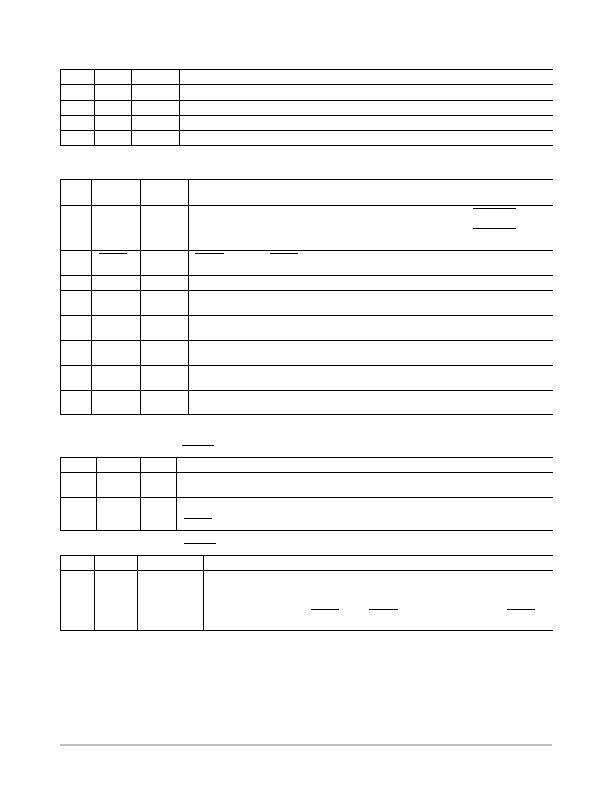
Table 87. REGISTER 0x77 Extended Resolution Register 2 (Note 36) (PowerOn Default = 0x00)
Bit
Name
R/W
Description
<1:0>
12 V
R
12 V LSBs. Holds the 2 LSBs of the 10bit 12 V measurement.
<3:2>
TDM1
R
Remote 1 Temperature LSBs. Holds the 2 LSBs of the 10bit Remote 1 temperature measurement.
<5:4>
LTMP
R
Local Temperature LSBs. Holds the 2 LSBs of the 10bit local temperature measurement.
<7:6>
TDM2
R
Remote 2 Temperature LSBs. Holds the 2 LSBs of the 10bit Remote 2 temperature measurement.
36.If this register is read, this register and the registers holding the MSB of each reading are frozen until read.
Table 88. REGISTER 0x78 Configuration Register 3 (PowerOn Default = 0x00)
Bit
Name
R/W
(Note 37)
Description
<0>
ALERT
R/W
ALERT = 1, Pin 10 on the QSOP package, Pin 7 on the QFN package (PWM2/SMBALERT
) is
configured as an SMBALERT
interrupt output to indicate outoflimit error conditions.
ALERT = 0, Pin 10 on the QSOP package, Pin 7 on the QFN package (PWM2/SMBALERT
) is
configured as the PWM2 output.
<1>
THERM
/
2.5 V
R/W
THERM
= 1 enables THERM
functionality on Pin 22 on the QSOP package, Pin 19 on the QFN
package
<2>
Reserved
R
<3>
FAST
R/W
FAST = 1 enables fast TACH measurements on all channels. This increases the TACH measure-
ment rate from once per second to once every 250 ms (4 x).
<4>
DC1
R/W
DC1 = 1 enables TACH measurements to be continuously made on TACH1. Fans must be driven
by dc. Setting this bit prevents pulse stretching because it is not required for dcdriven motors.
<5>
DC2
R/W
DC2 = 1 enables TACH measurements to be continuously made on TACH2. Fans must be driven
by dc. Setting this bit prevents pulse stretching because it is not required for dcdriven motors.
<6>
DC3
R/W
DC3 = 1 enables TACH measurements to be continuously made on TACH3. Setting this bit pre-
vents pulse stretching because it is not required for dcdriven motors.
<7>
DC4
R/W
DC4 = 1 enables TACH measurements to be continuously made on TACH4. Setting this bit pre-
vents pulse stretching because it is not required for dcdriven motors.
37.Bits <3:0> of this register become readonly when the Configuration Register 1 lock bit is set to 1. Any further attempts to write to bits <3:0>
have no effect.
Table 89. REGISTER 0x79 THERM
Timer Value Register (PowerOn Default = 0x00)
Bit
Name
R/W
Description
<7:1>
TMR
R
Times how long THERM
input is asserted. These seven bits read zero until the THERM
assertion time
exceeds 45.52 ms.
<0>
ASRT/
TMR0
R
This bit is set high on the assertion of the THERM
input and is cleared on read. If the THERM
asser-
tion time exceeds 45.52 ms, this bit is set and becomes the LSB of the 8bit TMR reading. This allows
THERM
assertion times from 45.52 ms to 5.82 sec to be reported back with a resolution of 22.76 ms.
Table 90. REGISTER 0x7A THERM
Timer Limit Register (PowerOn Default = 0xFF)
Bit
Name
R/W
Description
<7:0>
LIMT
R/W
Sets maximum THERM
assertion length allowed before an interrupt is generated. This is an
8bit limit with a resolution of 22.76 ms allowing THERM
assertion limits of 45.52 ms to 5.82 s
to be programmed. If the THERM
assertion time exceeds this limit, Bit 5 (F4P) of Interrupt
Status Register 2 (Reg. 0x42) is set. If the limit value is 0x00, an interrupt is generated immedi-
ately on the assertion of the THERM
input. If THERM
is configured as an output the THERM
timer limit should be set to 0xFF to avoid unwanted alerts from being generated.
相關(guān)PDF資料 |
PDF描述 |
|---|---|
| NCT75MNR2G | IC SENSOR TEMP DGTL 8DFN |
| NCV8881PWR2G | IC REG TRPL BUCK/LINEAR 16SOIC |
| NE1617ADS,112 | IC TEMP MONITOR 16SSOP |
| NE1619DS,118 | IC TEMP MONITOR 16SSOP |
| NIS5112D1R2G | IC ELECTRONIC FUSE HOTSWAP 8SOIC |
相關(guān)代理商/技術(shù)參數(shù) |
參數(shù)描述 |
|---|---|
| NCT75DMR2G | 功能描述:板上安裝溫度傳感器 2-Channel Digital Thermometer w/ Alarm RoHS:否 制造商:Omron Electronics 輸出類(lèi)型:Digital 配置: 準(zhǔn)確性:+/- 1.5 C, +/- 3 C 溫度閾值: 數(shù)字輸出 - 總線接口:2-Wire, I2C, SMBus 電源電壓-最大:5.5 V 電源電壓-最小:4.5 V 最大工作溫度:+ 50 C 最小工作溫度:0 C 關(guān)閉: 安裝風(fēng)格: 封裝 / 箱體: 設(shè)備功能:Temperature and Humidity Sensor |
| NCT75DR2G | 功能描述:板上安裝溫度傳感器 2-Channel Digital Thermometer w/ Alarm RoHS:否 制造商:Omron Electronics 輸出類(lèi)型:Digital 配置: 準(zhǔn)確性:+/- 1.5 C, +/- 3 C 溫度閾值: 數(shù)字輸出 - 總線接口:2-Wire, I2C, SMBus 電源電壓-最大:5.5 V 電源電壓-最小:4.5 V 最大工作溫度:+ 50 C 最小工作溫度:0 C 關(guān)閉: 安裝風(fēng)格: 封裝 / 箱體: 設(shè)備功能:Temperature and Humidity Sensor |
| NCT75MNR2G | 功能描述:板上安裝溫度傳感器 HAS2MONOJLCC84SPACE RoHS:否 制造商:Omron Electronics 輸出類(lèi)型:Digital 配置: 準(zhǔn)確性:+/- 1.5 C, +/- 3 C 溫度閾值: 數(shù)字輸出 - 總線接口:2-Wire, I2C, SMBus 電源電壓-最大:5.5 V 電源電壓-最小:4.5 V 最大工作溫度:+ 50 C 最小工作溫度:0 C 關(guān)閉: 安裝風(fēng)格: 封裝 / 箱體: 設(shè)備功能:Temperature and Humidity Sensor |
| NCT7717U TR | 制造商:Nuvoton Technology Corp 功能描述:SMBUS INTERFACE TEMP. SENSOR W 制造商:Nuvoton Technology Corp 功能描述:IC SMBUS TEMP SENSOR 8MSOP |
| NCT7718W TR | 制造商:Nuvoton Technology Corp 功能描述:IC SMBUS TEMP SENSOR 8MSOP |
發(fā)布緊急采購(gòu),3分鐘左右您將得到回復(fù)。