- 您現(xiàn)在的位置:買賣IC網(wǎng) > Datasheet目錄45 > NCT7491RQR2G (ON Semiconductor)IC REMOTE THERMAL MONITOR 24QSOP Datasheet資料下載
參數(shù)資料
| 型號(hào): | NCT7491RQR2G |
| 廠商: | ON Semiconductor |
| 文件頁數(shù): | 26/80頁 |
| 文件大小: | 844K |
| 描述: | IC REMOTE THERMAL MONITOR 24QSOP |
| 標(biāo)準(zhǔn)包裝: | 2,500 |
| 系列: | * |
第1頁第2頁第3頁第4頁第5頁第6頁第7頁第8頁第9頁第10頁第11頁第12頁第13頁第14頁第15頁第16頁第17頁第18頁第19頁第20頁第21頁第22頁第23頁第24頁第25頁當(dāng)前第26頁第27頁第28頁第29頁第30頁第31頁第32頁第33頁第34頁第35頁第36頁第37頁第38頁第39頁第40頁第41頁第42頁第43頁第44頁第45頁第46頁第47頁第48頁第49頁第50頁第51頁第52頁第53頁第54頁第55頁第56頁第57頁第58頁第59頁第60頁第61頁第62頁第63頁第64頁第65頁第66頁第67頁第68頁第69頁第70頁第71頁第72頁第73頁第74頁第75頁第76頁第77頁第78頁第79頁第80頁
NCT7491
http://onsemi.com
26
PWM
1
Temperature
2
3 4 5
1
2
3
4
5
100%
6,7,8
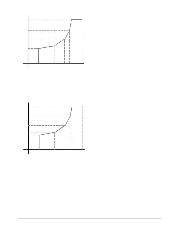
Figure 12.
0癈
255癈
Figure 12 shows a typical lookup table curve. The
temperatures are programmed as unsigned data. In this
example 5 of the 8 control points are used and the remaining
3 are set to the maximum value of 255癈. This curve applies
if relative PECI values are not
assigned to control the PWM
channel.
PWM
1
Temperature
2
3 4 5
1
2
3
4
5
100%
6,7,8
Figure 13.
128癈
0癈
Figure 13 shows a typical lookup table curve that applies
when relative PECI values are assigned to control the PWM
channel. The temperatures are programmed as negative 2s
complement values. In this example 5 of the 8 control points
are used and the remaining 3 are set to the maximum value
of 0癈, as this is the maximum value for relative PECI
values.
Fan Override Settings
There are bits in the NCT7491 that allow the PWM
outputs to be overdriven so that the outputs go to maximum
speed (as programmed in the maximum PWM registers), to
go to full speed (100% duty) or to be shut off. These bits will
override all other fan control settings.
" Setting bit 1 of register 0x11 to 1 runs the fans at the
maximum programmed PWM duty cycle
" Setting bit 3 of register 0x40 to 1 runs the fans at 100%
duty cycle. This bit has precedence over all others.
" Setting bit 0 of register 0x87 to 1 turns off PWM1
" Setting bit 1 of register 0x87 to 1 turns off PWM2
" Setting bit 2 of register 0x87 to 1 turns off PWM3
THERM Override
Setting bit 5 of register 0x40 will allow assertions on any
pin configured as a THERM pin to drive the fans to 100%
duty cycle or Max PWM, deending on bits <4:2> of register
0x16. This will override all other fan settings. This allows an
external device to bypass the register settings of the
NCT7491 for fail safe operation.
Fan Drive
The NCT7491 uses pulse width modulation (PWM) to
control fan speed. This relies on varying the duty cycle (or
on/off ratio) of a square wave applied to the fan to vary the
fan speed. The external circuitry required to drive a fan using
PWM control is extremely simple. For 4wire fans, the
PWM drive may need only a pullup resistor. In many cases
the 4wire fan PWM input has an internal pullup resistor.
The NCT7491 PWM frequency can be set to a selection of
low frequencies or a single high PWM frequency. The low
frequency options are used for 3wire fans, while the high
frequency option is usually used with 4wire fans. For
3wire fans, a single Nchannel MOSFET is the only drive
device required. The specifications of the MOSFET depend
on the maximum current required by the fan being driven
and the input capacitance of the FET. Because a 10 k (or
greater) resistor must be used as a PWM pullup, an FET with
large input capacitance can cause the PWM output to
become distorted and adversely affect the fan control range.
This is a requirement only when using high frequency PWM
mode. Typical notebook fans draw a nominal 170 mA,
therefore, SOT devices can be used where board space is a
concern. In desktops, fans typically draw 250 mA to 300 mA
each. If several fans are driven in parallel from a single
PWM output or drive larger server fans, the MOSFET must
handle the higher current requirements. The only other
stipulation is that the MOSFET should have a gate voltage
drive, VGS < 3.3 V, for direct interfacing to the PWM output
pin.
相關(guān)PDF資料 |
PDF描述 |
|---|---|
| NCT75MNR2G | IC SENSOR TEMP DGTL 8DFN |
| NCV8881PWR2G | IC REG TRPL BUCK/LINEAR 16SOIC |
| NE1617ADS,112 | IC TEMP MONITOR 16SSOP |
| NE1619DS,118 | IC TEMP MONITOR 16SSOP |
| NIS5112D1R2G | IC ELECTRONIC FUSE HOTSWAP 8SOIC |
相關(guān)代理商/技術(shù)參數(shù) |
參數(shù)描述 |
|---|---|
| NCT75DMR2G | 功能描述:板上安裝溫度傳感器 2-Channel Digital Thermometer w/ Alarm RoHS:否 制造商:Omron Electronics 輸出類型:Digital 配置: 準(zhǔn)確性:+/- 1.5 C, +/- 3 C 溫度閾值: 數(shù)字輸出 - 總線接口:2-Wire, I2C, SMBus 電源電壓-最大:5.5 V 電源電壓-最小:4.5 V 最大工作溫度:+ 50 C 最小工作溫度:0 C 關(guān)閉: 安裝風(fēng)格: 封裝 / 箱體: 設(shè)備功能:Temperature and Humidity Sensor |
| NCT75DR2G | 功能描述:板上安裝溫度傳感器 2-Channel Digital Thermometer w/ Alarm RoHS:否 制造商:Omron Electronics 輸出類型:Digital 配置: 準(zhǔn)確性:+/- 1.5 C, +/- 3 C 溫度閾值: 數(shù)字輸出 - 總線接口:2-Wire, I2C, SMBus 電源電壓-最大:5.5 V 電源電壓-最小:4.5 V 最大工作溫度:+ 50 C 最小工作溫度:0 C 關(guān)閉: 安裝風(fēng)格: 封裝 / 箱體: 設(shè)備功能:Temperature and Humidity Sensor |
| NCT75MNR2G | 功能描述:板上安裝溫度傳感器 HAS2MONOJLCC84SPACE RoHS:否 制造商:Omron Electronics 輸出類型:Digital 配置: 準(zhǔn)確性:+/- 1.5 C, +/- 3 C 溫度閾值: 數(shù)字輸出 - 總線接口:2-Wire, I2C, SMBus 電源電壓-最大:5.5 V 電源電壓-最小:4.5 V 最大工作溫度:+ 50 C 最小工作溫度:0 C 關(guān)閉: 安裝風(fēng)格: 封裝 / 箱體: 設(shè)備功能:Temperature and Humidity Sensor |
| NCT7717U TR | 制造商:Nuvoton Technology Corp 功能描述:SMBUS INTERFACE TEMP. SENSOR W 制造商:Nuvoton Technology Corp 功能描述:IC SMBUS TEMP SENSOR 8MSOP |
| NCT7718W TR | 制造商:Nuvoton Technology Corp 功能描述:IC SMBUS TEMP SENSOR 8MSOP |
發(fā)布緊急采購,3分鐘左右您將得到回復(fù)。