- 您現(xiàn)在的位置:買賣IC網(wǎng) > PDF目錄45010 > M30240M4-XXXFP 16-BIT, MROM, MICROCONTROLLER, PQFP80 PDF資料下載
參數(shù)資料
| 型號: | M30240M4-XXXFP |
| 元件分類: | 微控制器/微處理器 |
| 英文描述: | 16-BIT, MROM, MICROCONTROLLER, PQFP80 |
| 封裝: | 0.80 MM PITCH, PLASTIC, QFP-80 |
| 文件頁數(shù): | 62/125頁 |
| 文件大小: | 753K |
| 代理商: | M30240M4-XXXFP |
第1頁第2頁第3頁第4頁第5頁第6頁第7頁第8頁第9頁第10頁第11頁第12頁第13頁第14頁第15頁第16頁第17頁第18頁第19頁第20頁第21頁第22頁第23頁第24頁第25頁第26頁第27頁第28頁第29頁第30頁第31頁第32頁第33頁第34頁第35頁第36頁第37頁第38頁第39頁第40頁第41頁第42頁第43頁第44頁第45頁第46頁第47頁第48頁第49頁第50頁第51頁第52頁第53頁第54頁第55頁第56頁第57頁第58頁第59頁第60頁第61頁當前第62頁第63頁第64頁第65頁第66頁第67頁第68頁第69頁第70頁第71頁第72頁第73頁第74頁第75頁第76頁第77頁第78頁第79頁第80頁第81頁第82頁第83頁第84頁第85頁第86頁第87頁第88頁第89頁第90頁第91頁第92頁第93頁第94頁第95頁第96頁第97頁第98頁第99頁第100頁第101頁第102頁第103頁第104頁第105頁第106頁第107頁第108頁第109頁第110頁第111頁第112頁第113頁第114頁第115頁第116頁第117頁第118頁第119頁第120頁第121頁第122頁第123頁第124頁第125頁
Mitsubishi microcomputers
M16C / 24 Group
SINGLE-CHIP 16-BIT CMOS MICROCOMPUTER
43
CONFIDENTIAL
Preliminary Specifications REV.B
Specifications in this manual are tentative and subject to change
Frequency Synthesizer Circuit
The FSC0 bit in the FSC Control Register enables the frequency synthesizer block. When disabled
(FSC0 = "0"), fVCO is held at either a high or low state. When the frequency synthesizer control bit is
active (FSC0 = "1"), a lock status (LS = "1") indicates that fSYN and fVCO are the correct frequency. The
LS and FSCO control bits in the FSC Control register are shown in Figure 27.
When using the frequency synthesizer, a low-pass filter must be connected to the LPF pin.
Once the frequency synthesizer is enabled, a delay of 2-5ms is recommended before the output of the
frequency synthesizer is used. This is done to allow the output to stabilize. It is also recommended that
none of the registers be modified once the frequency synthesizer is enabled as it will cause the output
to be temporarily (2-5ms) unstable. The CPU and USB clock sources are selecxted via the Frequency
Synthesizer Clock Control register (FSCCR). See Figure 28
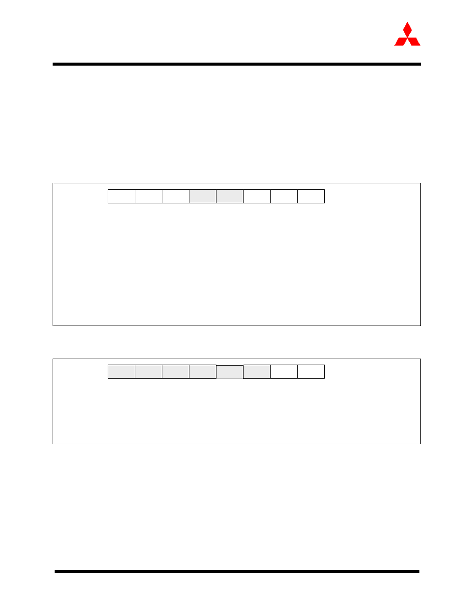
Figure 27:
Frequency Synthesizer Control Register (FSC)
Figure 28:
Frequency Synthesizer Clock Control Register (FSCCR)
FSE
Frequency Synthesizer Enable - Bit 0
0: Disabled
1: Enabled
VCO1,0
VCO Gain Control - Bits 2,1
Bit 2
Bit 1
0
0:
Lowest Gain (recommended)
0
1:
Low Gain
1
0:
High Gain
1
1:
Highest Gain
Bits 4,3
Reserved (Read/Write “0”)
CHG1,0
LPF Current Control - Bits 6,5
Bit 6
Bit 5
0
0:
Disabled
0
1:
Low Current
1
0:
Intermediate Current (recommended)
1
1:
High Current
LS
Frequency Synthesizer Lock Status (Read Only; Write “0”) - Bit 7
0: Unlocked
1: Locked
MSB
7
LSB
0
CHG0
VCO0
FSE
Address: 03DC16
Access: R/W
Reset:
6016
VCO1
LS
CHG1
Reserved
FSCCR0
Clock Source Selection- Bit 0
0: Xin
1: fSYN
FSCCR1
USB Clock Source Selection- Bit 1
0: fUSB = fVCO
1: fUSB = fXin
Bits 7-2
Reserved (Read/Write “0”)
MSB
7
LSB
0
FSCCR1
FSCCR0
Address: 03DB16
Access: R/W
Reset:
0016
Reserved
相關(guān)PDF資料 |
PDF描述 |
|---|---|
| M30240M1-XXXFP | 16-BIT, MROM, MICROCONTROLLER, PQFP80 |
| M30245MC-XXXGP | 16-BIT, MROM, 16 MHz, MICROCONTROLLER, PQFP100 |
| M30245FCGP | 16-BIT, FLASH, 16 MHz, MICROCONTROLLER, PQFP100 |
| M30260F3VGP | 16-BIT, FLASH, 20 MHz, MICROCONTROLLER, PQFP48 |
| M30260M3A-XXXGP-U5 | 16-BIT, FLASH, 20 MHz, MICROCONTROLLER, PQFP48 |
相關(guān)代理商/技術(shù)參數(shù) |
參數(shù)描述 |
|---|---|
| M30240M5 | 制造商:MITSUBISHI 制造商全稱:Mitsubishi Electric Semiconductor 功能描述:SINGLE-CHIP 16-BIT CMOS MICROCOMPUTER |
| M30240M5-XXXFP | 制造商:MITSUBISHI 制造商全稱:Mitsubishi Electric Semiconductor 功能描述:SINGLE-CHIP 16-BIT CMOS MICROCOMPUTER |
| M30240M6 | 制造商:MITSUBISHI 制造商全稱:Mitsubishi Electric Semiconductor 功能描述:SINGLE-CHIP 16-BIT CMOS MICROCOMPUTER |
| M30240M6-XXXFP | 制造商:MITSUBISHI 制造商全稱:Mitsubishi Electric Semiconductor 功能描述:SINGLE-CHIP 16-BIT CMOS MICROCOMPUTER |
| M30240M7 | 制造商:MITSUBISHI 制造商全稱:Mitsubishi Electric Semiconductor 功能描述:SINGLE-CHIP 16-BIT CMOS MICROCOMPUTER |
發(fā)布緊急采購,3分鐘左右您將得到回復。