- 您現(xiàn)在的位置:買賣IC網(wǎng) > PDF目錄97930 > EPF8482A Programmable Logic PDF資料下載
參數(shù)資料
| 型號: | EPF8482A |
| 英文描述: | Programmable Logic |
| 中文描述: | 可編程邏輯 |
| 文件頁數(shù): | 20/61頁 |
| 文件大小: | 979K |
| 代理商: | EPF8482A |
第1頁第2頁第3頁第4頁第5頁第6頁第7頁第8頁第9頁第10頁第11頁第12頁第13頁第14頁第15頁第16頁第17頁第18頁第19頁當前第20頁第21頁第22頁第23頁第24頁第25頁第26頁第27頁第28頁第29頁第30頁第31頁第32頁第33頁第34頁第35頁第36頁第37頁第38頁第39頁第40頁第41頁第42頁第43頁第44頁第45頁第46頁第47頁第48頁第49頁第50頁第51頁第52頁第53頁第54頁第55頁第56頁第57頁第58頁第59頁第60頁第61頁
Altera Corporation
27
FLEX 8000 Programmable Logic Device Family Data Sheet
FLEX
8000
3
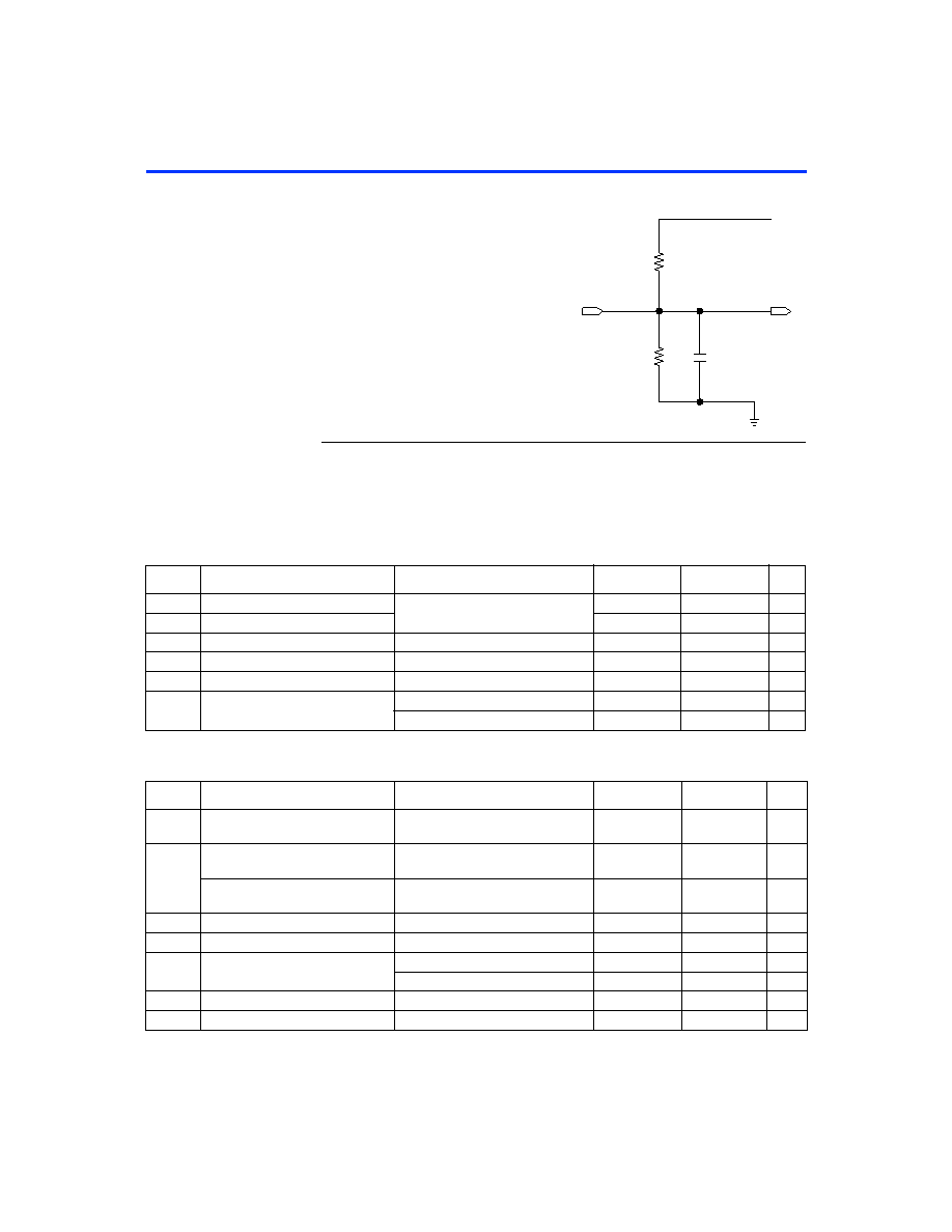
Figure 15. FLEX 8000 AC Test Conditions
Operating
Conditions
The following tables provide information on absolute maximum ratings,
recommended operating conditions, operating conditions, and
capacitance for 5.0-V and 3.3-V FLEX 8000 devices.
FLEX 8000 5.0-V Device Absolute Maximum Ratings
FLEX 8000 5.0-V Device Recommended Operating Conditions
VCC
to Test
System
C1 (includes
JIG capacitance)
Device input
rise and fall
times < 3 ns
464
(703
)
Device
Output
250
(8.06 K
)
Power supply transients can affect AC
measurements. Simultaneous transitions of
multiple outputs should be avoided for
accurate measurement. Threshold tests
must not be performed under AC
conditions.
Large-amplitude, fast-ground-current
transients normally occur as the device
outputs discharge the load capacitances.
When these transients ow through the
parasitic inductance between the device
ground pin and the test system ground,
signicant reductions in observable noise
immunity can result. Numbers in
Symbol
Parameter
Conditions
Min
Max
Unit
VCC
Supply voltage
With respect to ground,
–2.0
7.0
V
VI
DC input voltage
–2.0
7.0
V
IOUT
DC output current, per pin
–25
25
mA
TSTG
Storage temperature
No bias
–65
150
° C
TAMB
Ambient temperature
Under bias
–65
135
° C
TJ
Junction temperature
Ceramic packages, under bias
150
° C
PQFP and RQFP, under bias
135
° C
Symbol
Parameter
Conditions
Min
Max
Unit
VCCINT
Supply voltage for internal logic and
input buffers
4.75 (4.50)
5.25 (5.50)
V
VCCIO
Supply voltage for output buffers,
5.0-V operation
4.75 (4.50)
5.25 (5.50)
V
Supply voltage for output buffers,
3.3-V operation
3.00 (3.00)
3.60 (3.60)
V
VI
Input voltage
0
VCCINT
V
VO
Output voltage
0
VCCIO
V
TA
Operating temperature
For commercial use
0
70
° C
For industrial use
–40
85
° C
tR
Input rise time
40
ns
tF
Input fall time
40
ns
相關(guān)PDF資料 |
PDF描述 |
|---|---|
| EPIC | EPiC Family Product Line (304k) |
| EPL10P8BD | UV-Erasable/OTP PLD |
| EPL10P8BP | UV-Erasable/OTP PLD |
| EPL12P6BD | UV-Erasable/OTP PLD |
| EPL241ED | UV-Erasable/OTP PLD |
相關(guān)代理商/技術(shù)參數(shù) |
參數(shù)描述 |
|---|---|
| EPF8636A | 制造商:ALTERA 制造商全稱:Altera Corporation 功能描述:Programmable Logic Device Family |
| EPF8636AGC192-2 | 制造商:未知廠家 制造商全稱:未知廠家 功能描述:Field Programmable Gate Array (FPGA) |
| EPF8636AGC192-3 | 制造商:未知廠家 制造商全稱:未知廠家 功能描述:Field Programmable Gate Array (FPGA) |
| EPF8636AGC192-4 | 制造商:Altera Corporation 功能描述:Field-Programmable Gate Array, 504 Cell, 192 Pin, Ceramic, PGA |
| EPF8636AGC192-5 | 制造商:Altera Corporation 功能描述:Field-Programmable Gate Array, 504 Cell, 192 Pin, Ceramic, PGA |
發(fā)布緊急采購,3分鐘左右您將得到回復。