- 您現(xiàn)在的位置:買賣IC網 > PDF目錄4591 > DS34T104GN+ (Maxim Integrated Products)IC TDM OVER PACKET 484TEBGA PDF資料下載
參數資料
| 型號: | DS34T104GN+ |
| 廠商: | Maxim Integrated Products |
| 文件頁數: | 148/366頁 |
| 文件大?。?/td> | 0K |
| 描述: | IC TDM OVER PACKET 484TEBGA |
| 產品培訓模塊: | Lead (SnPb) Finish for COTS Obsolescence Mitigation Program |
| 標準包裝: | 30 |
| 類型: | TDM(分時復用) |
| 應用: | 數據傳輸 |
| 安裝類型: | 表面貼裝 |
| 封裝/外殼: | 484-BGA |
| 供應商設備封裝: | 484-TEBGA(23x23) |
| 包裝: | 托盤 |
第1頁第2頁第3頁第4頁第5頁第6頁第7頁第8頁第9頁第10頁第11頁第12頁第13頁第14頁第15頁第16頁第17頁第18頁第19頁第20頁第21頁第22頁第23頁第24頁第25頁第26頁第27頁第28頁第29頁第30頁第31頁第32頁第33頁第34頁第35頁第36頁第37頁第38頁第39頁第40頁第41頁第42頁第43頁第44頁第45頁第46頁第47頁第48頁第49頁第50頁第51頁第52頁第53頁第54頁第55頁第56頁第57頁第58頁第59頁第60頁第61頁第62頁第63頁第64頁第65頁第66頁第67頁第68頁第69頁第70頁第71頁第72頁第73頁第74頁第75頁第76頁第77頁第78頁第79頁第80頁第81頁第82頁第83頁第84頁第85頁第86頁第87頁第88頁第89頁第90頁第91頁第92頁第93頁第94頁第95頁第96頁第97頁第98頁第99頁第100頁第101頁第102頁第103頁第104頁第105頁第106頁第107頁第108頁第109頁第110頁第111頁第112頁第113頁第114頁第115頁第116頁第117頁第118頁第119頁第120頁第121頁第122頁第123頁第124頁第125頁第126頁第127頁第128頁第129頁第130頁第131頁第132頁第133頁第134頁第135頁第136頁第137頁第138頁第139頁第140頁第141頁第142頁第143頁第144頁第145頁第146頁第147頁當前第148頁第149頁第150頁第151頁第152頁第153頁第154頁第155頁第156頁第157頁第158頁第159頁第160頁第161頁第162頁第163頁第164頁第165頁第166頁第167頁第168頁第169頁第170頁第171頁第172頁第173頁第174頁第175頁第176頁第177頁第178頁第179頁第180頁第181頁第182頁第183頁第184頁第185頁第186頁第187頁第188頁第189頁第190頁第191頁第192頁第193頁第194頁第195頁第196頁第197頁第198頁第199頁第200頁第201頁第202頁第203頁第204頁第205頁第206頁第207頁第208頁第209頁第210頁第211頁第212頁第213頁第214頁第215頁第216頁第217頁第218頁第219頁第220頁第221頁第222頁第223頁第224頁第225頁第226頁第227頁第228頁第229頁第230頁第231頁第232頁第233頁第234頁第235頁第236頁第237頁第238頁第239頁第240頁第241頁第242頁第243頁第244頁第245頁第246頁第247頁第248頁第249頁第250頁第251頁第252頁第253頁第254頁第255頁第256頁第257頁第258頁第259頁第260頁第261頁第262頁第263頁第264頁第265頁第266頁第267頁第268頁第269頁第270頁第271頁第272頁第273頁第274頁第275頁第276頁第277頁第278頁第279頁第280頁第281頁第282頁第283頁第284頁第285頁第286頁第287頁第288頁第289頁第290頁第291頁第292頁第293頁第294頁第295頁第296頁第297頁第298頁第299頁第300頁第301頁第302頁第303頁第304頁第305頁第306頁第307頁第308頁第309頁第310頁第311頁第312頁第313頁第314頁第315頁第316頁第317頁第318頁第319頁第320頁第321頁第322頁第323頁第324頁第325頁第326頁第327頁第328頁第329頁第330頁第331頁第332頁第333頁第334頁第335頁第336頁第337頁第338頁第339頁第340頁第341頁第342頁第343頁第344頁第345頁第346頁第347頁第348頁第349頁第350頁第351頁第352頁第353頁第354頁第355頁第356頁第357頁第358頁第359頁第360頁第361頁第362頁第363頁第364頁第365頁第366頁
____________________________________________________ DS34T101, DS34T102, DS34T104, DS34T108
231 of 366
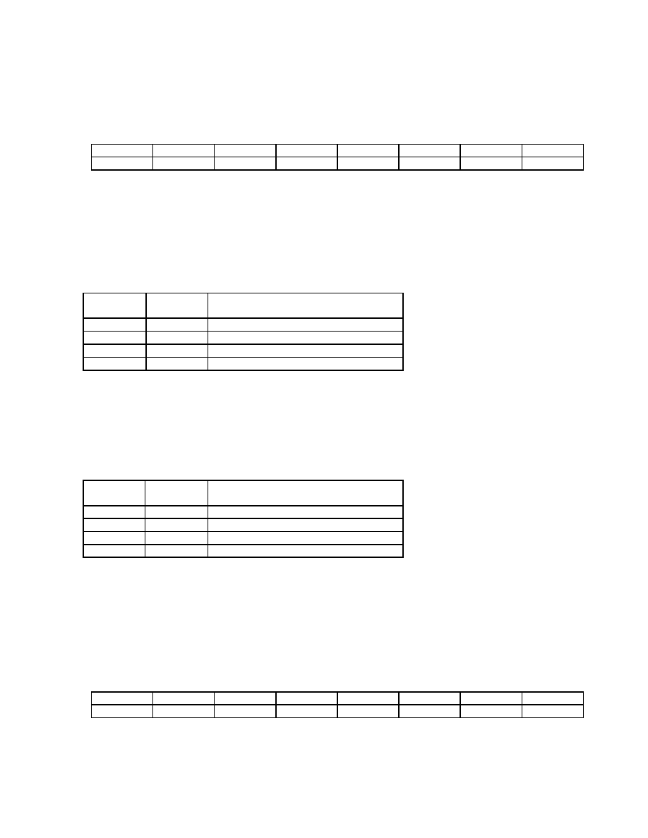
Register Name:
RBOCC
Register Description:
Receive BOC Control Register (T1 Mode Only)
Register Address:
base address + 0x054
Bit #
7
6
5
4
3
2
1
0
Name
RBR
-
RBD1
RBD0
RIE
RBF1
RBF0
-
Default
0
Bit 7: Rx BOC Reset (RBR). Setting this bit to 1 forces a reset of the BOC circuitry. Note that this is an
acknowledged reset – the CPU sets the bit and the device clears it after the reset operation is complete (less than
250
s). Modifications to the RBF[1:0] and RBD[1:0] fields are ignored by the BOC controller until a BOC reset has
been completed. See section 10.11.4.2.
Bits 5, 4: Rx BOC Disintegration (RBD[1:0]). The BOC disintegration filter sets the number of message bits that
must be received without a valid BOC before the RLS7.BC bit is set to indicate that a valid BOC is no longer being
received. See section 10.11.4.2.
RBD1
RBD0
CONSECUTIVE MESSAGE BITS
FOR BOC CLEAR IDENTIFICATION
0
16
0
1
32
1
0
48
1
64
1
Bit 3: RBOC 7/10 Integration Enable (RBI). This bit enables RBOC 7 of 10 integration. See section 10.11.4.2.
0 = 7/10 integration disable
1 = 7/10 integration enabled
Bits 2, 1: Rx BOC Filter bits (RBF[1:0]). The BOC filter sets the number of consecutive BOC codes that must be
received without error before the RLS7-T1.BD bit is set to indicate that a valid BOC is being received. See section
RBF1
RBF0
CONSECUTIVE BOC CODES FOR
VALID SEQUENCE IDENTIFICATION
0
None
0
1
3
1
0
5
1
7
1
Note 1. The BOC controller does not integrate and disintegrate concurrently. Therefore, if the maximum integration
and disintegration times are taken together, BOC messages that repeat fewer than 11 times may not be detected.
Register Name:
RIDR1 to RIDR32
Register Description:
Receive Idle Code Definition Registers 1 to 32
Register Address:
base address + 0x080 + 0x04*(n-1), n = channel number = 1 to 32
Bit #
7
6
5
4
3
2
1
0
Name
C7
C6
C5
C4
C3
C2
C1
C0
Default
0
Bits 7 to 0: Per-Channel Idle Code Bits (C[7:0]). C0 is the LSB of the code (this bit is transmitted last). Address
0x80 holds the idle code for channel 1. Address 0xDC is for channel 24. Address 0xFC is for channel 32. Note that
相關PDF資料 |
PDF描述 |
|---|---|
| DS34T101GN+ | IC TDM OVER PACKET 484TEBGA |
| MIC2211-GOYML TR | IC REG LDO 1.8V/2.9V 10-MLF |
| MIC2211-GJYML TR | IC REG LDO 1.8V/2.5V 10-MLF |
| MIC2211-SGYML TR | IC REG LDO 3.3V/1.8V 10-MLF |
| MIC2211-GPYML TR | IC REG LDO 1.8V/3V 10-MLF |
相關代理商/技術參數 |
參數描述 |
|---|---|
| DS34T104GN+ | 功能描述:通信集成電路 - 若干 Quad TDM Over Packet Chip RoHS:否 制造商:Maxim Integrated 類型:Transport Devices 封裝 / 箱體:TECSBGA-256 數據速率:100 Mbps 電源電壓-最大:1.89 V, 3.465 V 電源電壓-最小:1.71 V, 3.135 V 電源電流:50 mA, 225 mA 最大工作溫度:+ 85 C 最小工作溫度:- 40 C 封裝:Tube |
| DS34T108 | 制造商:MAXIM 制造商全稱:Maxim Integrated Products 功能描述:Single/Dual/Quad/Octal TDM-over-Packet Chip |
| DS34T108DK-L1 | 功能描述:以太網開發(fā)工具 RoHS:否 制造商:Micrel 產品:Evaluation Boards 類型:Ethernet Transceivers 工具用于評估:KSZ8873RLL 接口類型:RMII 工作電源電壓: |
發(fā)布緊急采購,3分鐘左右您將得到回復。