- 您現(xiàn)在的位置:買賣IC網(wǎng) > PDF目錄376802 > DM9102 (Electronic Theatre Controls, Inc.) Single Chip Fast Ethernet NIC controller PDF資料下載
參數(shù)資料
| 型號: | DM9102 |
| 廠商: | Electronic Theatre Controls, Inc. |
| 英文描述: | Single Chip Fast Ethernet NIC controller |
| 中文描述: | 單芯片快速以太網(wǎng)網(wǎng)卡控制器 |
| 文件頁數(shù): | 49/77頁 |
| 文件大小: | 459K |
| 代理商: | DM9102 |
第1頁第2頁第3頁第4頁第5頁第6頁第7頁第8頁第9頁第10頁第11頁第12頁第13頁第14頁第15頁第16頁第17頁第18頁第19頁第20頁第21頁第22頁第23頁第24頁第25頁第26頁第27頁第28頁第29頁第30頁第31頁第32頁第33頁第34頁第35頁第36頁第37頁第38頁第39頁第40頁第41頁第42頁第43頁第44頁第45頁第46頁第47頁第48頁當前第49頁第50頁第51頁第52頁第53頁第54頁第55頁第56頁第57頁第58頁第59頁第60頁第61頁第62頁第63頁第64頁第65頁第66頁第67頁第68頁第69頁第70頁第71頁第72頁第73頁第74頁第75頁第76頁第77頁

DM9102A
Single Chip Fast Ethernet NIC controller
Final
Version: DM9102A-DS-F03
August 28, 2000
49
Functional Description
System Buffer Management
1.Overview
The data buffers for reception and transmission of data
resides in the host memory. They are directed by the
descriptor list that is located in another region of the host
memory. All actions for the buffer management are operated
by the DM9102A in conjunction with the driver. The data
structures and processing algorithms are described in the
following text.
2. Data Structure and Descriptor List
There are two types of buffers that reside in the host
memory, the transmit buffer and the receive buffer. The
buffers are composed of many distributed regions in the
host memory. They are linked together and controlled by the
descriptor lists that reside in another region of the host
memory. The content of each descriptor includes pointer to
the buffer, count of the buffer, command and status for the
packet to be transmitted or received. Each descriptor list
starts from the address setting of CR3 (receive descriptor
base address) and CR4 (transmit descriptor base address).
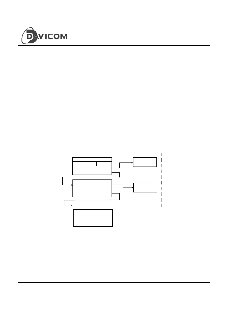
The descriptor list is Chain structure.
3. Buffer Management -- Chain Structure Method
As the Chain structure depicted below, each descriptor
contains two pointers, one point to a single buffer and the
other to the next descriptor chained. The first descriptor is
chained to the last descriptor under host driver’s control.
With this structure, a descriptor can be allocated anywhere
in host memory and is chained to the next descriptor.
Buffer 1
Buffer 1
Descriptor 1
Descriptor N
Packet N
control
buffer address 1
status
own
not valid
next descriptor address
buffer 1 length
4. Descriptor List: Buffer Descriptor Format
(a). Receive Descriptor Format
Each receive descriptor has four double-word entries and
may be read or written by the host or the DM9102A. The
descriptor format is shown below with a detailed functional
description.
相關(guān)PDF資料 |
PDF描述 |
|---|---|
| DM9102A | Single Chip Fast Ethernet NIC controller |
| DM9102AF | Single Chip Fast Ethernet NIC controller |
| DM9102AT | Single Chip Fast Ethernet NIC controller |
| DM9108APPLICATIONENGINEERINGNOTESONE | DM9108 Application Engineering notes one |
| DM9108APPLICATIONENGINEERINGNOTESTHREE | DM9108 Application Engineering notes three |
相關(guān)代理商/技術(shù)參數(shù) |
參數(shù)描述 |
|---|---|
| DM9102A | 制造商:未知廠家 制造商全稱:未知廠家 功能描述:Single Chip Fast Ethernet NIC controller |
| DM9102AF | 制造商:未知廠家 制造商全稱:未知廠家 功能描述:Single Chip Fast Ethernet NIC controller |
| DM9102AT | 制造商:未知廠家 制造商全稱:未知廠家 功能描述:Single Chip Fast Ethernet NIC controller |
| DM9102D | 制造商:未知廠家 制造商全稱:未知廠家 功能描述:SINGLE CHIP FAST ETHEMET NIC CONTROLLER |
| DM9102DE | 制造商:DAVICOM 制造商全稱:DAVICOM 功能描述:Single Chip Fast Ethernet NIC Controller |
發(fā)布緊急采購,3分鐘左右您將得到回復(fù)。