- 您現(xiàn)在的位置:買賣IC網(wǎng) > PDF目錄382386 > PDI1394P25BY (NXP SEMICONDUCTORS) 1-port 400 Mbps physical layer interface PDF資料下載
參數(shù)資料
| 型號: | PDI1394P25BY |
| 廠商: | NXP SEMICONDUCTORS |
| 元件分類: | 網(wǎng)絡(luò)接口 |
| 英文描述: | 1-port 400 Mbps physical layer interface |
| 中文描述: | DATACOM, INTERFACE CIRCUIT, PQFP48 |
| 封裝: | 7 X 7 MM, 1.40 MM HEIGHT, PLASTIC, MS-026, SOT-313-2, LQFP-48 |
| 文件頁數(shù): | 23/42頁 |
| 文件大?。?/td> | 214K |
| 代理商: | PDI1394P25BY |
第1頁第2頁第3頁第4頁第5頁第6頁第7頁第8頁第9頁第10頁第11頁第12頁第13頁第14頁第15頁第16頁第17頁第18頁第19頁第20頁第21頁第22頁當(dāng)前第23頁第24頁第25頁第26頁第27頁第28頁第29頁第30頁第31頁第32頁第33頁第34頁第35頁第36頁第37頁第38頁第39頁第40頁第41頁第42頁

Philips Semiconductors
Product data
PDI1394P25BY
1-port 400 Mbps physical layer interface
2002 Oct 11
23
SV01808
C9
24.576 MHz
C10
XI
XO
ls
X1
C
PHY
+ C
BD
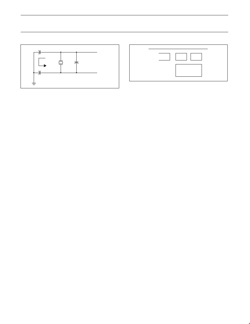
Figure 11.
Load Capacitance for the PDI1394P25 PHY
NOTE: The layout of the crystal portion of the PHY circuit is
important for obtaining the correct frequency, minimizing noise
introduced into the PHY’s Phase Lock Loop, and minimizing any
emissions from the circuit. The crystal and two load capacitors
should be considered as a unit during layout. The crystal and load
capacitors should be placed as close as possible to one another
while minimizing the loop area created by the combination of the
three components. Varying the size of the capacitors may help in
this. Minimizing the loop area minimizes the effect of the resonant
current (Is) that flows in this resonant circuit. This layout unit (crystal
and load capacitors) should then be placed as close as possible to
the PHY XI and XO terminals to minimize trace lengths.
SV01809
C9
C10
X1
Figure 12.
Recommended Crystal and Capacitor Layout
It is strongly recommended that part of the verification process for
the design be to measure the frequency of the SYSCLK output of
the PHY. This should be done with a frequency counter with an
accuracy of 6 digits or better. If the SYSCLK frequency is more than
the crystal’s tolerance from 49.152 MHz, the load capacitance of the
crystal may be varied to improve frequency accuracy. If the
frequency is too high add more load capacitance; if the frequency is
too low decrease load capacitance. Typically, changes should be
done to both load capacitors (C9 and C10 above) at the same time,
and both should be of the same value. Additional design details and
requirements may be provided by the crystal vendor.
相關(guān)PDF資料 |
PDF描述 |
|---|---|
| PDI20AC1H0R | |
| PDI20AC1H0X | |
| PDI20AC1HR0 | |
| PDI20AC1HRX | |
| PDI20AC1L0R | |
相關(guān)代理商/技術(shù)參數(shù) |
參數(shù)描述 |
|---|---|
| PDI1394P25EC | 制造商:PHILIPS 制造商全稱:NXP Semiconductors 功能描述:1-port 400 Mbps physical layer interface |
| PDI-15R | 制造商:Power Dynamics Inc 功能描述: |
| PDI-15RH-5 | 制造商:Power Dynamics Inc 功能描述: |
| PDI-15RH-5-R-G30 | 制造商:Power Dynamics Inc 功能描述:PDI Series 15 Position Right Angle Socket High Density D-Sub |
| PDI-15S | 制造商:POWER DYNAMICS 功能描述: 制造商:Power Dynamics Inc 功能描述: |
發(fā)布緊急采購,3分鐘左右您將得到回復(fù)。