- 您現(xiàn)在的位置:買賣IC網(wǎng) > PDF目錄45317 > MQ80C154-16P883 (TEMIC SEMICONDUCTORS) 8-BIT, 16 MHz, MICROCONTROLLER, CQFP44 PDF資料下載
參數(shù)資料
| 型號(hào): | MQ80C154-16P883 |
| 廠商: | TEMIC SEMICONDUCTORS |
| 元件分類: | 微控制器/微處理器 |
| 英文描述: | 8-BIT, 16 MHz, MICROCONTROLLER, CQFP44 |
| 文件頁數(shù): | 74/142頁 |
| 文件大小: | 61013K |
| 代理商: | MQ80C154-16P883 |
第1頁第2頁第3頁第4頁第5頁第6頁第7頁第8頁第9頁第10頁第11頁第12頁第13頁第14頁第15頁第16頁第17頁第18頁第19頁第20頁第21頁第22頁第23頁第24頁第25頁第26頁第27頁第28頁第29頁第30頁第31頁第32頁第33頁第34頁第35頁第36頁第37頁第38頁第39頁第40頁第41頁第42頁第43頁第44頁第45頁第46頁第47頁第48頁第49頁第50頁第51頁第52頁第53頁第54頁第55頁第56頁第57頁第58頁第59頁第60頁第61頁第62頁第63頁第64頁第65頁第66頁第67頁第68頁第69頁第70頁第71頁第72頁第73頁當(dāng)前第74頁第75頁第76頁第77頁第78頁第79頁第80頁第81頁第82頁第83頁第84頁第85頁第86頁第87頁第88頁第89頁第90頁第91頁第92頁第93頁第94頁第95頁第96頁第97頁第98頁第99頁第100頁第101頁第102頁第103頁第104頁第105頁第106頁第107頁第108頁第109頁第110頁第111頁第112頁第113頁第114頁第115頁第116頁第117頁第118頁第119頁第120頁第121頁第122頁第123頁第124頁第125頁第126頁第127頁第128頁第129頁第130頁第131頁第132頁第133頁第134頁第135頁第136頁第137頁第138頁第139頁第140頁第141頁第142頁
165
ATmega165A/PA/325A/PA/3250A/PA/645A/P/6450A/P [DATASHEET]
8285E–AVR–02/2013
starts looking for the next high to low-transition. If however, a valid start bit is detected, the clock recovery logic is
synchronized and the data recovery can begin. The synchronization process is repeated for each start bit.
20.8.2
Asynchronous Data Recovery
When the receiver clock is synchronized to the start bit, the data recovery can begin. The data recovery unit uses a
state machine that has 16 states for each bit in Normal mode and eight states for each bit in Double Speed mode.
Figure 20-6 on page 165 shows the sampling of the data bits and the parity bit. Each of the samples is given a
number that is equal to the state of the recovery unit.
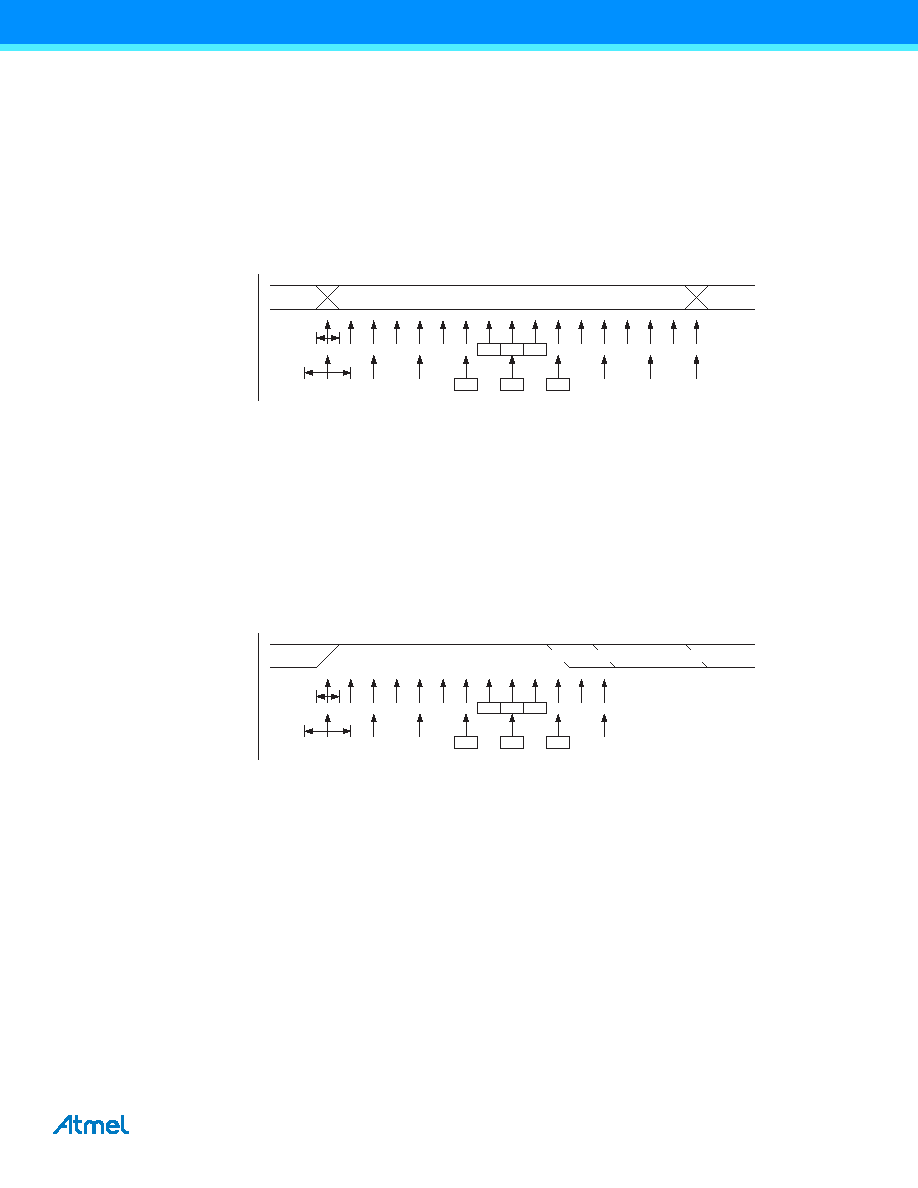
Figure 20-6. Sampling of Data and Parity Bit
The decision of the logic level of the received bit is taken by doing a majority voting of the logic value to the three
samples in the center of the received bit. The center samples are emphasized on the figure by having the sample
number inside boxes. The majority voting process is done as follows: If two or all three samples have high levels,
the received bit is registered to be a logic 1. If two or all three samples have low levels, the received bit is regis-
tered to be a logic 0. This majority voting process acts as a low pass filter for the incoming signal on the RxD pin.
The recovery process is then repeated until a complete frame is received. Including the first stop bit. Note that the
Receiver only uses the first stop bit of a frame.
Figure 20-7 on page 165 shows the sampling of the stop bit and the earliest possible beginning of the start bit of
the next frame.
Figure 20-7. Stop Bit Sampling and Next Start Bit Sampling.
The same majority voting is done to the stop bit as done for the other bits in the frame. If the stop bit is registered to
have a logic 0 value, the Frame Error (FEn) Flag will be set.
A new high to low transition indicating the start bit of a new frame can come right after the last of the bits used for
majority voting. For Normal Speed mode, the first low level sample can be at point marked (A) in Figure 20-7 on
page 165. For Double Speed mode the first low level must be delayed to (B). (C) marks a stop bit of full length. The
early start bit detection influences the operational range of the Receiver.
20.8.3
Asynchronous Operational Range
The operational range of the Receiver is dependent on the mismatch between the received bit rate and the inter-
nally generated baud rate. If the Transmitter is sending frames at too fast or too slow bit rates, or the internally
generated baud rate of the Receiver does not have a similar (see Table 20-2 on page 166) base frequency, the
Receiver will not be able to synchronize the frames to the start bit.
12
34
56
7
8
9
10
11
12
13
14
15
16
1
BIT n
123
4
5
678
1
RxD
Sample
(U2X = 0)
Sample
(U2X = 1)
12
34
56
7
8
9
10
0/1
STOP 1
123
4
5
6
0/1
RxD
Sample
(U2X = 0)
Sample
(U2X = 1)
(A)
(B)
(C)
相關(guān)PDF資料 |
PDF描述 |
|---|---|
| MQ83C154XXX-L16/883D | 8-BIT, MROM, 16 MHz, MICROCONTROLLER, CQFP44 |
| MQ83C154CXXX-25/883R | 8-BIT, MROM, 25 MHz, MICROCONTROLLER, CQFP44 |
| MR80C154-L16/883R | 8-BIT, 16 MHz, MICROCONTROLLER, CQCC44 |
| MQ83C154CXXX-L16P883R | 8-BIT, MROM, 16 MHz, MICROCONTROLLER, CQFP44 |
| MR83C154CXXX-20P883R | 8-BIT, MROM, 20 MHz, MICROCONTROLLER, CQCC44 |
相關(guān)代理商/技術(shù)參數(shù) |
參數(shù)描述 |
|---|---|
| MQ80C154-20 | 制造商:TEMIC 制造商全稱:TEMIC Semiconductors 功能描述:CMOS 0 to 36 MHz Single Chip 8-bit Microcontroller |
| MQ80C154-25 | 制造商:TEMIC 制造商全稱:TEMIC Semiconductors 功能描述:CMOS 0 to 36 MHz Single Chip 8-bit Microcontroller |
| MQ80C154-30 | 制造商:TEMIC 制造商全稱:TEMIC Semiconductors 功能描述:CMOS 0 to 36 MHz Single Chip 8-bit Microcontroller |
| MQ80C154-36 | 制造商:TEMIC 制造商全稱:TEMIC Semiconductors 功能描述:CMOS 0 to 36 MHz Single Chip 8-bit Microcontroller |
| MQ80C154-L16 | 制造商:TEMIC 制造商全稱:TEMIC Semiconductors 功能描述:CMOS 0 to 36 MHz Single Chip 8-bit Microcontroller |
發(fā)布緊急采購(gòu),3分鐘左右您將得到回復(fù)。