- 您現(xiàn)在的位置:買賣IC網(wǎng) > PDF目錄45317 > MQ80C154-16P883 (TEMIC SEMICONDUCTORS) 8-BIT, 16 MHz, MICROCONTROLLER, CQFP44 PDF資料下載
參數(shù)資料
| 型號: | MQ80C154-16P883 |
| 廠商: | TEMIC SEMICONDUCTORS |
| 元件分類: | 微控制器/微處理器 |
| 英文描述: | 8-BIT, 16 MHz, MICROCONTROLLER, CQFP44 |
| 文件頁數(shù): | 132/142頁 |
| 文件大?。?/td> | 61013K |
| 代理商: | MQ80C154-16P883 |
第1頁第2頁第3頁第4頁第5頁第6頁第7頁第8頁第9頁第10頁第11頁第12頁第13頁第14頁第15頁第16頁第17頁第18頁第19頁第20頁第21頁第22頁第23頁第24頁第25頁第26頁第27頁第28頁第29頁第30頁第31頁第32頁第33頁第34頁第35頁第36頁第37頁第38頁第39頁第40頁第41頁第42頁第43頁第44頁第45頁第46頁第47頁第48頁第49頁第50頁第51頁第52頁第53頁第54頁第55頁第56頁第57頁第58頁第59頁第60頁第61頁第62頁第63頁第64頁第65頁第66頁第67頁第68頁第69頁第70頁第71頁第72頁第73頁第74頁第75頁第76頁第77頁第78頁第79頁第80頁第81頁第82頁第83頁第84頁第85頁第86頁第87頁第88頁第89頁第90頁第91頁第92頁第93頁第94頁第95頁第96頁第97頁第98頁第99頁第100頁第101頁第102頁第103頁第104頁第105頁第106頁第107頁第108頁第109頁第110頁第111頁第112頁第113頁第114頁第115頁第116頁第117頁第118頁第119頁第120頁第121頁第122頁第123頁第124頁第125頁第126頁第127頁第128頁第129頁第130頁第131頁當(dāng)前第132頁第133頁第134頁第135頁第136頁第137頁第138頁第139頁第140頁第141頁第142頁
217
ATmega165A/PA/325A/PA/3250A/PA/645A/P/6450A/P [DATASHEET]
8285E–AVR–02/2013
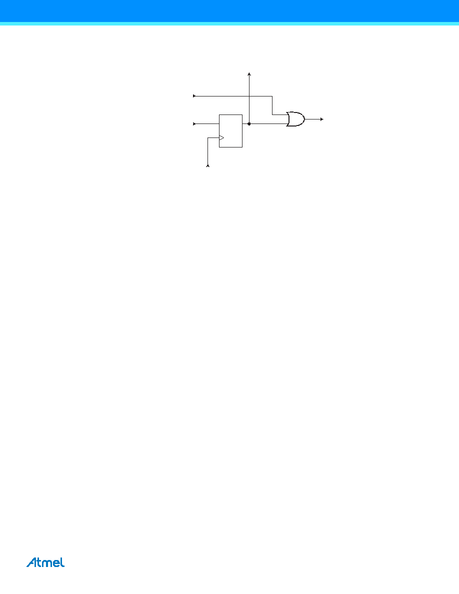
Figure 25-2. Reset Register.
25.3.4
Boundary-scan Chain
The Boundary-scan Chain has the capability of driving and observing the logic levels on the digital I/O pins, as well
as the boundary between digital and analog logic for analog circuitry having off-chip connections.
See ”Boundary-scan Chain” on page 218 for a complete description.
25.4
Boundary-scan Specific JTAG Instructions
The Instruction Register is 4-bit wide, supporting up to 16 instructions. Listed below are the JTAG instructions use-
ful for Boundary-scan operation. Note that the optional HIGHZ instruction is not implemented, but all outputs with
tri-state capability can be set in high-impedant state by using the AVR_RESET instruction, since the initial state for
all port pins is tri-state.
As a definition in this datasheet, the LSB is shifted in and out first for all Shift Registers.
The OPCODE for each instruction is shown behind the instruction name in hex format. The text describes which
Data Register is selected as path between TDI and TDO for each instruction.
25.4.1
EXTEST; 0x0
Mandatory JTAG instruction for selecting the Boundary-scan Chain as Data Register for testing circuitry external to
the AVR package. For port-pins, Pull-up Disable, Output Control, Output Data, and Input Data are all accessible in
the scan chain. For Analog circuits having off-chip connections, the interface between the analog and the digital
logic is in the scan chain. The contents of the latched outputs of the Boundary-scan chain is driven out as soon as
the JTAG IR-Register is loaded with the EXTEST instruction.
The active states are:
Capture-DR: Data on the external pins are sampled into the Boundary-scan Chain
Shift-DR: The Internal Scan Chain is shifted by the TCK input
Update-DR: Data from the scan chain is applied to output pins
25.4.2
IDCODE; 0x1
Optional JTAG instruction selecting the 32 bit ID-Register as Data Register. The ID-Register consists of a version
number, a device number and the manufacturer code chosen by JEDEC. This is the default instruction after power-
up.
The active states are:
Capture-DR: Data in the IDCODE Register is sampled into the Boundary-scan Chain
Shift-DR: The IDCODE scan chain is shifted by the TCK input
DQ
From
TDI
ClockDR AVR_RESET
To
TDO
From Other Internal and
External Reset Sources
Internal reset
相關(guān)PDF資料 |
PDF描述 |
|---|---|
| MQ83C154XXX-L16/883D | 8-BIT, MROM, 16 MHz, MICROCONTROLLER, CQFP44 |
| MQ83C154CXXX-25/883R | 8-BIT, MROM, 25 MHz, MICROCONTROLLER, CQFP44 |
| MR80C154-L16/883R | 8-BIT, 16 MHz, MICROCONTROLLER, CQCC44 |
| MQ83C154CXXX-L16P883R | 8-BIT, MROM, 16 MHz, MICROCONTROLLER, CQFP44 |
| MR83C154CXXX-20P883R | 8-BIT, MROM, 20 MHz, MICROCONTROLLER, CQCC44 |
相關(guān)代理商/技術(shù)參數(shù) |
參數(shù)描述 |
|---|---|
| MQ80C154-20 | 制造商:TEMIC 制造商全稱:TEMIC Semiconductors 功能描述:CMOS 0 to 36 MHz Single Chip 8-bit Microcontroller |
| MQ80C154-25 | 制造商:TEMIC 制造商全稱:TEMIC Semiconductors 功能描述:CMOS 0 to 36 MHz Single Chip 8-bit Microcontroller |
| MQ80C154-30 | 制造商:TEMIC 制造商全稱:TEMIC Semiconductors 功能描述:CMOS 0 to 36 MHz Single Chip 8-bit Microcontroller |
| MQ80C154-36 | 制造商:TEMIC 制造商全稱:TEMIC Semiconductors 功能描述:CMOS 0 to 36 MHz Single Chip 8-bit Microcontroller |
| MQ80C154-L16 | 制造商:TEMIC 制造商全稱:TEMIC Semiconductors 功能描述:CMOS 0 to 36 MHz Single Chip 8-bit Microcontroller |
發(fā)布緊急采購,3分鐘左右您將得到回復(fù)。