- 您現(xiàn)在的位置:買賣IC網(wǎng) > PDF目錄98158 > TAS3204PAG (TEXAS INSTRUMENTS INC) SPECIALTY CONSUMER CIRCUIT, PQFP64 PDF資料下載
參數(shù)資料
| 型號: | TAS3204PAG |
| 廠商: | TEXAS INSTRUMENTS INC |
| 元件分類: | 消費(fèi)家電 |
| 英文描述: | SPECIALTY CONSUMER CIRCUIT, PQFP64 |
| 封裝: | GREEN, PLASTIC, TQFP-64 |
| 文件頁數(shù): | 34/76頁 |
| 文件大小: | 1224K |
| 代理商: | TAS3204PAG |
第1頁第2頁第3頁第4頁第5頁第6頁第7頁第8頁第9頁第10頁第11頁第12頁第13頁第14頁第15頁第16頁第17頁第18頁第19頁第20頁第21頁第22頁第23頁第24頁第25頁第26頁第27頁第28頁第29頁第30頁第31頁第32頁第33頁當(dāng)前第34頁第35頁第36頁第37頁第38頁第39頁第40頁第41頁第42頁第43頁第44頁第45頁第46頁第47頁第48頁第49頁第50頁第51頁第52頁第53頁第54頁第55頁第56頁第57頁第58頁第59頁第60頁第61頁第62頁第63頁第64頁第65頁第66頁第67頁第68頁第69頁第70頁第71頁第72頁第73頁第74頁第75頁第76頁

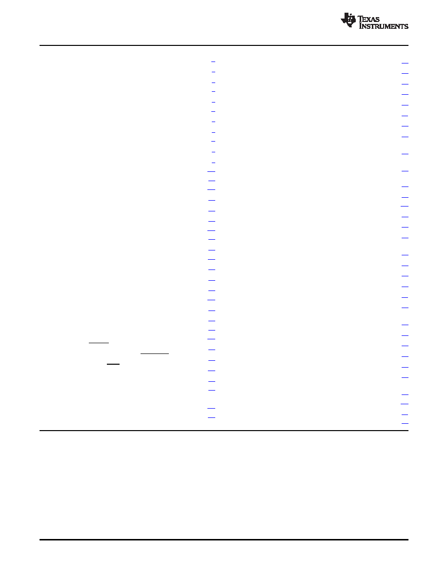
SLES197C – APRIL 2007 – REVISED MARCH 2011
www.ti.com
1
Introduction
.............................................. 1
11.1
Absolute Maximum Ratings
........................ 39
1.1
Features
.............................................. 1
11.2
Package Dissipation Ratings
....................... 39
1.2
Applications
.......................................... 1
11.3
Recommended Operating Conditions
.............. 39
1.3
Description
........................................... 2
11.4
Electrical Characteristics
........................... 40
1.4
Ordering Information
................................. 3
11.5
Audio Specifications
................................ 40
2
Physical Characteristics
............................... 5
11.6
Timing Characteristics
.............................. 43
2.1
Terminal Assignments
............................... 5
11.7
Master Clock
........................................ 43
2.2
Terminal Descriptions
................................ 6
11.8
Serial Audio Port, Slave Mode
..................... 44
3
TAS3204 Clocking System
............................ 8
11.9
Serial Audio Port Master Mode Signals (TAS3204)
3.1
Core Clock Management
............................ 8
...................................................... 45
11.10
Pin-Related Characteristics of the SDA and SCL
3.2
SAP Clock Management
............................. 9
I/O Stages for F/S-Mode I2C-Bus Devices
......... 46
4
Digital Audio Interface
................................ 11
11.11
Bus-Related Characteristics of the SDA and SCL
4.1
Serial Audio Port (SAP)
............................ 11
I/O Stages for F/S-Mode I2C-Bus Devices
......... 46
5
Analog Audio Interface
............................... 17
11.12
Reset Timing
...................................... 48
5.1
Analog to Digital Converters ADCs
................. 17
12
I
2C Register Map
....................................... 49
5.2
Digital to Analog Converters DACs
................. 17
12.1
Clock Control Register (0x00)
...................... 50
5.3
Analog Reference System
.......................... 17
12.2
MCUcontroller Clock Control Register
.............. 50
6
Embedded MCUcontroller
........................... 18
12.3
Status Register (0x02)
.............................. 51
6.1
MCU Addressing Modes
............................ 18
12.4
I2C Memory Load Control and Data Registers (0x04
6.2
Boot Up Sequence
................................. 19
and 0x05)
........................................... 52
7
Digital Audio Processor
.............................. 20
12.5
Memory Access Registers (0x06 and 0x07)
........ 53
7.1
Audio Digital Signal Processor Core
............... 22
12.6
Device Version (0x08)
.............................. 54
7.2
DAP Instructions Set
............................... 22
12.7
Analog Power Down Control (0x10 and 0x11)
..... 54
7.3
DAP Data Word Structure
.......................... 23
12.8
Analog Input Control (0x12)
........................ 55
8
I
2C Control Interface
.................................. 25
12.9
Dynamic Element Matching (0x13)
................. 55
8.1
General I2C Operations
............................. 25
12.10
Current Control Select (0x14, 0x15, 0x17, 0x18)
8.2
I2C Master Interface
................................ 26
...................................................... 56
8.3
I2C Slave Mode Operation
.......................... 31
12.11
DAC Control (0x1A, 0x1B, 0x1D)
................. 60
9
TAS3204 Control Pins
................................ 35
12.12
ADC and DAC Reset (0x1E)
...................... 62
9.1
Reset (RESET) - Power-Up Sequence
............. 35
12.13
ADC Input Gain Control (0x1F)
................... 62
9.2
Voltage Regulator Enable (VREG_EN)
............ 35
12.14
MCLK_OUT Divider (0x21 and 0x22)
............. 63
9.3
Power Down (PDN)
................................. 35
12.15
Digital Cross Bar (0x30 to 0x3F)
.................. 63
9.4
I2C Bus Control (CS0)
.............................. 36
12.16
Extended Special Function Registers (ESFR) Map
9.5
Programmable I/O (GPIO)
.......................... 36
...................................................... 65
10
Algorithm and Software Development Tools for
13
Application Information
.............................. 70
TAS3204
................................................. 38
13.1
Schematics
......................................... 70
11
Electrical Specifications
............................. 39
13.2
Recommended Oscillator Circuit
................... 71
4
Contents
Copyright 2007–2011, Texas Instruments Incorporated
Product Folder Link(s): TAS3204
相關(guān)PDF資料 |
PDF描述 |
|---|---|
| TAS3218IPZPR | SPECIALTY CONSUMER CIRCUIT, PQFP100 |
| TAS3218IPZP | SPECIALTY CONSUMER CIRCUIT, PQFP100 |
| TAS3218PZPR | SPECIALTY CONSUMER CIRCUIT, PQFP100 |
| TAS3218PZP | SPECIALTY CONSUMER CIRCUIT, PQFP100 |
| TAS5000PFB | SPECIALTY CONSUMER CIRCUIT, PQFP48 |
相關(guān)代理商/技術(shù)參數(shù) |
參數(shù)描述 |
|---|---|
| TAS3204PAGR | 功能描述:音頻 DSP Hi Perf Dual Core DSP/MCU Aud Proc RoHS:否 制造商:Texas Instruments 工作電源電壓: 電源電流: 工作溫度范圍: 安裝風(fēng)格: 封裝 / 箱體: 封裝:Tube |
| TAS3208 | 制造商:TI 制造商全稱:Texas Instruments 功能描述:DIGITAL AUDIO PROCESSOR WITH ANALOG INTERFACE |
| TAS3208EVM | 功能描述:音頻 IC 開發(fā)工具 TAS3208EVM Eval Mod RoHS:否 制造商:Texas Instruments 產(chǎn)品:Evaluation Kits 類型:Audio Amplifiers 工具用于評估:TAS5614L 工作電源電壓:12 V to 38 V |
| TAS3208EVM-LC | 功能描述:音頻 IC 開發(fā)工具 TAS3208 Low Cost EVM RoHS:否 制造商:Texas Instruments 產(chǎn)品:Evaluation Kits 類型:Audio Amplifiers 工具用于評估:TAS5614L 工作電源電壓:12 V to 38 V |
| TAS3208IPZP | 功能描述:音頻 DSP Dual Core Dig Aud Proc RoHS:否 制造商:Texas Instruments 工作電源電壓: 電源電流: 工作溫度范圍: 安裝風(fēng)格: 封裝 / 箱體: 封裝:Tube |
發(fā)布緊急采購,3分鐘左右您將得到回復(fù)。
