- 您現(xiàn)在的位置:買賣IC網(wǎng) > PDF目錄98068 > S1C60N04D 4-BIT, MROM, 2 MHz, MICROCONTROLLER, UUC48 PDF資料下載
參數(shù)資料
| 型號: | S1C60N04D |
| 元件分類: | 微控制器/微處理器 |
| 英文描述: | 4-BIT, MROM, 2 MHz, MICROCONTROLLER, UUC48 |
| 封裝: | DIE-48 |
| 文件頁數(shù): | 3/50頁 |
| 文件大小: | 372K |
| 代理商: | S1C60N04D |
第1頁第2頁當(dāng)前第3頁第4頁第5頁第6頁第7頁第8頁第9頁第10頁第11頁第12頁第13頁第14頁第15頁第16頁第17頁第18頁第19頁第20頁第21頁第22頁第23頁第24頁第25頁第26頁第27頁第28頁第29頁第30頁第31頁第32頁第33頁第34頁第35頁第36頁第37頁第38頁第39頁第40頁第41頁第42頁第43頁第44頁第45頁第46頁第47頁第48頁第49頁第50頁

S1C60N04 TECHNICAL MANUAL
EPSON
5
CHAPTER 2: POWER SUPPLY AND INITIAL RESET
2.2.1 Power-on reset circuit
The power-on reset circuit outputs the initial reset signal at power-on until the oscillation circuit starts
oscillating.
Note: The power-on reset circuit may not work properly due to unstable or lower voltage input. The
following two initial reset method are recommended to generate the initial reset signal.
2.2.2 Reset pin (RESET)
An initial reset can be invoked externally by making the reset pin high.
When the reset pin goes low the CPU begins to operate.
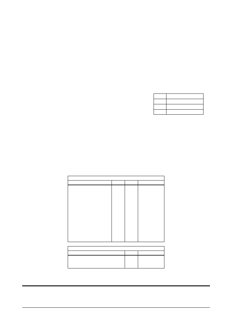
2.2.3 Simultaneous high input to input ports (K00–K03)
A
Not used
B
K00*K01
C
K00*K01*K02
D
K00*K01*K02*K03
When, for instance, mask option D (K00*K01*K02*K03) is selected, an initial reset is executed when the
signals input to the four ports K00–K03 are all high at the same time.
When this function is used, make sure that the specified ports do not go high at the same time during
normal operation.
2.2.4 Internal register following initialization
An initial reset initializes the CPU as shown in the table below.
Table 2.2.4.1 Initial values
See Section 4.1, "Memory Map".
Name
Program counter step
Program counter page
New page pointer
Stack pointer
Index register X
Index register Y
Register pointer
General-purpose register A
General-purpose register B
Interrupt flag
Decimal flag
Zero flag
Carry flag
CPU Core
Symbol
PCS
PCP
NPP
SP
X
Y
RP
A
B
I
D
Z
C
Bit size
8
4
8
4
1
Initial value
00H
1H
Undefined
0
Undefined
Name
RAM
Display memory
Other peripheral circuits
Peripheral Circuits
Bit size
144
×4
26
×4
–
Initial value
Undefined
2.3 Test Pin (TEST)
This pin is used when IC is inspected for shipment. During normal operation connect it to VSS.
Another way of invoking an initial reset externally is to input a
high signal simultaneously to the input ports (K00–K03) selected
with the mask option. The specified input port pins must be kept
high for at least 1 sec (when oscillating frequency fosc = 2 MHz),
tolerance is within 5%, because of the noise rejection circuit. Table
2.2.3.1 shows the combinations of input ports (K00–K03) that can be
selected with the mask option.
Table 2.2.3.1 Input port combinations
相關(guān)PDF資料 |
PDF描述 |
|---|---|
| S1C60N08D | 4-BIT, MROM, 0.032768 MHz, MICROCONTROLLER, UUC96 |
| S1C60N08F0A0100 | MICROCONTROLLER, PQFP100 |
| S1C621C0D | 4-BIT, MROM, 1.3 MHz, MICROCONTROLLER, UUC74 |
| S1C62480D | 4-BIT, MROM, 2.3 MHz, MICROCONTROLLER, UUC135 |
| S1C62440F | 4-BIT, MROM, 2.3 MHz, MICROCONTROLLER, PQFP128 |
相關(guān)代理商/技術(shù)參數(shù) |
參數(shù)描述 |
|---|---|
| S1C60N05 | 制造商:EPSON 制造商全稱:EPSON 功能描述:4-bit Single Chip Microcomputer |
| S1C60N08 | 制造商:EPSON 制造商全稱:EPSON 功能描述:4-bit Single Chip Microcomputer |
| S1C60N16 | 制造商:EPSON 制造商全稱:EPSON 功能描述:4-bit Single Chip Microcomputer |
| S1C60R08 | 制造商:EPSON 制造商全稱:EPSON 功能描述:4-bit Single Chip Microcomputer |
| S1C63004 | 制造商:EPSON 制造商全稱:EPSON 功能描述:CMOS 4-bit Single Chip Microcontroller |
發(fā)布緊急采購,3分鐘左右您將得到回復(fù)。