- 您現(xiàn)在的位置:買賣IC網(wǎng) > PDF目錄382377 > PCA5010 (NXP Semiconductors N.V.) Pager baseband controller PDF資料下載
參數(shù)資料
| 型號: | PCA5010 |
| 廠商: | NXP Semiconductors N.V. |
| 英文描述: | Pager baseband controller |
| 中文描述: | 傳呼機基帶控制器 |
| 文件頁數(shù): | 43/112頁 |
| 文件大小: | 627K |
| 代理商: | PCA5010 |
第1頁第2頁第3頁第4頁第5頁第6頁第7頁第8頁第9頁第10頁第11頁第12頁第13頁第14頁第15頁第16頁第17頁第18頁第19頁第20頁第21頁第22頁第23頁第24頁第25頁第26頁第27頁第28頁第29頁第30頁第31頁第32頁第33頁第34頁第35頁第36頁第37頁第38頁第39頁第40頁第41頁第42頁當(dāng)前第43頁第44頁第45頁第46頁第47頁第48頁第49頁第50頁第51頁第52頁第53頁第54頁第55頁第56頁第57頁第58頁第59頁第60頁第61頁第62頁第63頁第64頁第65頁第66頁第67頁第68頁第69頁第70頁第71頁第72頁第73頁第74頁第75頁第76頁第77頁第78頁第79頁第80頁第81頁第82頁第83頁第84頁第85頁第86頁第87頁第88頁第89頁第90頁第91頁第92頁第93頁第94頁第95頁第96頁第97頁第98頁第99頁第100頁第101頁第102頁第103頁第104頁第105頁第106頁第107頁第108頁第109頁第110頁第111頁第112頁

1998 Nov 02
43
Philips Semiconductors
Product specification
Pager baseband controller
PCA5010
SFR:
TFREQ0 to TFREQ7: 8-bit register containing the
divisor of the tone. Loaded by the processor.
ENB: enable frequency generator. Control signal from
processor.
CLK2: use secondary clock input for tone generation.
If set a 32768 Hz clock signal is generated from the
primary 76800 Hz clock signal and used as a timing
reference for the tone generator.
Inputs:
76.8 kHz: Input to the tone counter.
Outputs:
AT Output for alerter. Is logic 0 when disabled:
TFREQ
6.15.3
G
ENERATION OF THE
32768 H
Z REFERENCE
The 32768 Hz reference is generated from 76800 Hz
according to the following algorithm:
forever do
begin
for 10 times do {
from 7 clocks on 76.8 kHz generate
3 pulses on 32 kHz
}
from 5 clocks on 76.8 kHz generate
2 pulses on 32 kHz
end
f
AT
76.8 kHz
=
6.16
Watchdog timer
6.16.1
F
UNCTION
The watchdog timer consists of an 8-bit down counter.
The binary number defined with WD3 to WD0 defines the
expiration time of the watchdog timer between 1 to 16 s.
Once enabled this counter is running continuously. Once
expired the timer produces firstly an interrupt and finally a
reset. The software must reload the watchdog in regular
intervals to avoid expiration.
A positive edge on the LD SFR bit (re)loads the counter
with the value of WD3 to WD0, sets the LOW bits to logic 1
and activates this counter if it is not yet running. However,
to prepare the (re)loading a positive edge must be applied
to the COND bit in WDCON. In this way at least two
locations in software must be passed before the counter
can be reloaded.
After reset the counter is not running. Only after the first LD
it is clocked continuously by a clock pulse of 16 Hz until the
DC/DC converter is switched off or an external reset is
applied.
If the next LD signal is not given within the defined expiry
interval an overflow occurs and the processor will be reset
(signal WDR). 1 clock cycle before the reset is applied an
WDI interrupt is issued. This gives the opportunity to avoid
the reset if required. The maximum watchdog expiry time
is thus 254
×
16 Hz ticks to the WD interrupt and
255
×
16 Hz ticks to the reset. If the DC/DC converter is in
the off mode, the watchdog timer is suspended.
6.16.2
W
ATCH
D
OG
T
IMER
C
ONTROL
R
EGISTER
(WDCON)
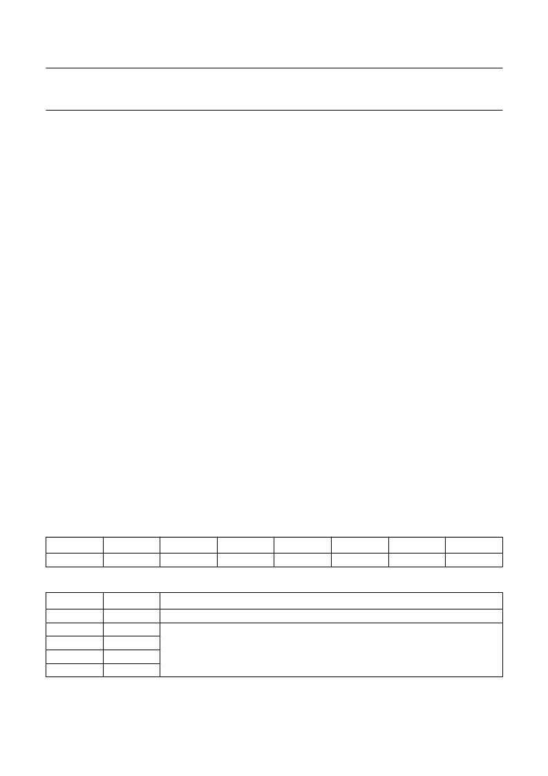
The WDCON special function register is used to control the operation of the on-chip watchdog timer.
Table 34
Watchdog Control Register (WDCON, SFR address A5H)
Table 35
Description of the WDCON bits
7
6
5
4
3
2
1
0
COND
WD3
WD2
WD1
WD0
LD
BIT
SYMBOL
FUNCTION
WDCON.7
WDCON.6
WDCON.5
WDCON.4
WDCON.3
COND
WD3
WD2
WD1
WD0
Load condition
. Control signal from processor.
WD0 to WD3 is the preset value for the high nibble of the watchdog timer. The value is
the number of seconds to expiry of the watchdog.
相關(guān)PDF資料 |
PDF描述 |
|---|---|
| PCA5010H | Pager baseband controller |
| PCA82C200 | STAND-ALONE CAN-CONTROLLER |
| PCA82C200P | STAND-ALONE CAN-CONTROLLER |
| PCA82C200T | STAND-ALONE CAN-CONTROLLER |
| PCA82C250 | CAN controller interface |
相關(guān)代理商/技術(shù)參數(shù) |
參數(shù)描述 |
|---|---|
| PCA5010H | 制造商:PHILIPS 制造商全稱:NXP Semiconductors 功能描述:Pager baseband controller |
| PCA5010H/XXX | 制造商:未知廠家 制造商全稱:未知廠家 功能描述:MICROCONTROLLER|8-BIT|8051 CPU|CMOS|QFP|48PIN|PLASTIC |
| PCA503HL320 | 制造商:ADAM-TECH 制造商全稱:Adam Technologies, Inc. 功能描述:ZIF FLEX CIRCUIT CONNECTOR |
| PCA503HU320 | 制造商:ADAM-TECH 制造商全稱:Adam Technologies, Inc. 功能描述:ZIF FLEX CIRCUIT CONNECTOR |
| PCA503V320 | 制造商:ADAM-TECH 制造商全稱:Adam Technologies, Inc. 功能描述:ZIF FLEX CIRCUIT CONNECTOR |
發(fā)布緊急采購,3分鐘左右您將得到回復(fù)。