- 您現(xiàn)在的位置:買賣IC網(wǎng) > PDF目錄45010 > M30240M1-XXXFP 16-BIT, MROM, MICROCONTROLLER, PQFP80 PDF資料下載
參數(shù)資料
| 型號: | M30240M1-XXXFP |
| 元件分類: | 微控制器/微處理器 |
| 英文描述: | 16-BIT, MROM, MICROCONTROLLER, PQFP80 |
| 封裝: | 0.80 MM PITCH, PLASTIC, QFP-80 |
| 文件頁數(shù): | 66/125頁 |
| 文件大小: | 753K |
| 代理商: | M30240M1-XXXFP |
第1頁第2頁第3頁第4頁第5頁第6頁第7頁第8頁第9頁第10頁第11頁第12頁第13頁第14頁第15頁第16頁第17頁第18頁第19頁第20頁第21頁第22頁第23頁第24頁第25頁第26頁第27頁第28頁第29頁第30頁第31頁第32頁第33頁第34頁第35頁第36頁第37頁第38頁第39頁第40頁第41頁第42頁第43頁第44頁第45頁第46頁第47頁第48頁第49頁第50頁第51頁第52頁第53頁第54頁第55頁第56頁第57頁第58頁第59頁第60頁第61頁第62頁第63頁第64頁第65頁當(dāng)前第66頁第67頁第68頁第69頁第70頁第71頁第72頁第73頁第74頁第75頁第76頁第77頁第78頁第79頁第80頁第81頁第82頁第83頁第84頁第85頁第86頁第87頁第88頁第89頁第90頁第91頁第92頁第93頁第94頁第95頁第96頁第97頁第98頁第99頁第100頁第101頁第102頁第103頁第104頁第105頁第106頁第107頁第108頁第109頁第110頁第111頁第112頁第113頁第114頁第115頁第116頁第117頁第118頁第119頁第120頁第121頁第122頁第123頁第124頁第125頁
Mitsubishi microcomputers
M16C / 24 Group
SINGLE-CHIP 16-BIT CMOS MICROCOMPUTER
47
CONFIDENTIAL
Preliminary Specifications REV.B
Specifications in this manual are tentative and subject to change
Universal Serial Bus
MAXP <= half of the IN FIFO size: When the number of bytes of data equal to the MAXP (maximum packet
size) is written to the IN FIFO by the CPU/DMAC, the USB FCU sets the TX_NOT_EMPTY/IN_PKT_RDY bits
to a “1” automatically depends on FIFO status. If only one packet of data is the FIFO TX_NOT_EMPTY bit
gets set to a ‘1’ and the IN_PKT_RDY bit get clear to a “0”. If two packets of data in the FIFO then both the
TX_NOT_EMPTY bit gets set to a “1” and the IN_PKT_RDY bit gets set to a “1” (the FIFO can hold up to two
data packets at the same time in this configuration, for back-to-back transmission). The CPU should only write
data to the IN FIFO if the IN_PKT_RDY bit of the IN CSR is a “0”.
A software or a hardware flush acts as if a packet is being successfully transmitted out to the host. If there is
one packet in the IN FIFO, a flush causes the IN FIFO to be empty, if there are two packets in the IN FIFO, a
flush causes the older packet to be flushed out from the IN FIFO. Flush updates the IN FIFO status
(IN_PKT_RDY and TX_NOT_EMPTY bits).
The status of the endpoint 1-4 IN FIFO for both of the above cases, could be obtained from the IN CSR as
shown in Table 12 .
Interrupt Endpoints:
Any endpoint can be used for interrupt transfers. For normal interrupt transfers, the interrupt transactions be-
have the same as bulk transactions, i.e., no special setting is required. The IN endpoints may also be used to
communicate rate feedback information for certain types of isochronous functions. This is done by setting the
INTPT bit in the IN CSR register of the corresponding endpoint. When the INTPT bit is set, the data toggle
bits is changed after each packet is sent to the host without regard to the presence or type of handshakepack-
et.
The following outlines the operation sequence for an IN endpoint used to communicate rate feedback infor-
mation:
1. Set MAXP > 1/2 of the endpoint’s FIFO size;
2. Set INTPT bit of the IN CSR;
3. Flush the old data in the FIFO;
4. Load interrupt status information and set IN_PKT_RDY bit in the IN CSR;
5. Repeat steps 3 & 4 for all subsequent interrupt status updates.
Out (Receive) FIFOs
The USB FCU writes data to the endpoint’s OUT FIFO location specified by the FIFO write pointer, which au-
tomatically increments by one after a write. When the USB FCU has successfully received a data packet, it
sets the OUT_PKT_RDY bit to a “1” in the OUT CSR. The CPU/DMAC only reads data from the OUT FIFO if
the OUT_PKT_RDY bit of the OUT CSR is a “1”.
Endpoint 0 OUT FIFO Operation:
The USB FCU sets the OUT_PKT_RDY bit to a ‘1’ after it has successfully received a packet of data from the
host. The CPU writes a “0” to the OUT_PKT_RDY bit after the packet of data is unloaded from the OUT FIFO
by the CPU.
Endpoint 1-4 OUT FIFO Operation when AUTO_CLR (bit 7 of OUT CSR) = “0”:
MAXP > half of the OUT FIFO size: The USB FCU sets the OUT_PKT_RDY bit to a “1” after it has successfully
received a packet of data from the host. The CPU writes a “0” to the OUT_PKT_RDY bit after the packet of
data is unloaded from the OUT FIFO by the CPU/DMAC.
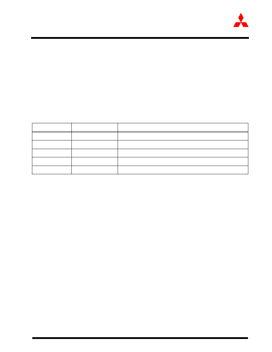
Table 12:
TA FIFO Status
IN_PKT_RDY
TX_NOT_EMPTY
TX FIFO Status
00
No data packet in TX FIFO
01
One data packet in TX FIFO if MAXP <= half of the FIFO size.
X1
One data packet in TX FIFO if MAXP >= half of the FIFO size.
10
Invalid
11
Two data packets in TX FIFO if MAXP <= half of the FIFO size
相關(guān)PDF資料 |
PDF描述 |
|---|---|
| M30245MC-XXXGP | 16-BIT, MROM, 16 MHz, MICROCONTROLLER, PQFP100 |
| M30245FCGP | 16-BIT, FLASH, 16 MHz, MICROCONTROLLER, PQFP100 |
| M30260F3VGP | 16-BIT, FLASH, 20 MHz, MICROCONTROLLER, PQFP48 |
| M30260M3A-XXXGP-U5 | 16-BIT, FLASH, 20 MHz, MICROCONTROLLER, PQFP48 |
| M30260M8A-XXXGP-U5 | 16-BIT, FLASH, 20 MHz, MICROCONTROLLER, PQFP48 |
相關(guān)代理商/技術(shù)參數(shù) |
參數(shù)描述 |
|---|---|
| M30240M2 | 制造商:MITSUBISHI 制造商全稱:Mitsubishi Electric Semiconductor 功能描述:SINGLE-CHIP 16-BIT CMOS MICROCOMPUTER |
| M30240M2-XXXFP | 制造商:MITSUBISHI 制造商全稱:Mitsubishi Electric Semiconductor 功能描述:SINGLE-CHIP 16-BIT CMOS MICROCOMPUTER |
| M30240M3 | 制造商:MITSUBISHI 制造商全稱:Mitsubishi Electric Semiconductor 功能描述:SINGLE-CHIP 16-BIT CMOS MICROCOMPUTER |
| M30240M3-XXXFP | 制造商:MITSUBISHI 制造商全稱:Mitsubishi Electric Semiconductor 功能描述:SINGLE-CHIP 16-BIT CMOS MICROCOMPUTER |
| M30240M4 | 制造商:MITSUBISHI 制造商全稱:Mitsubishi Electric Semiconductor 功能描述:SINGLE-CHIP 16-BIT CMOS MICROCOMPUTER |
發(fā)布緊急采購,3分鐘左右您將得到回復(fù)。