- 您現(xiàn)在的位置:買賣IC網(wǎng) > PDF目錄45010 > M30240M1-XXXFP 16-BIT, MROM, MICROCONTROLLER, PQFP80 PDF資料下載
參數(shù)資料
| 型號: | M30240M1-XXXFP |
| 元件分類: | 微控制器/微處理器 |
| 英文描述: | 16-BIT, MROM, MICROCONTROLLER, PQFP80 |
| 封裝: | 0.80 MM PITCH, PLASTIC, QFP-80 |
| 文件頁數(shù): | 10/125頁 |
| 文件大小: | 753K |
| 代理商: | M30240M1-XXXFP |
第1頁第2頁第3頁第4頁第5頁第6頁第7頁第8頁第9頁當(dāng)前第10頁第11頁第12頁第13頁第14頁第15頁第16頁第17頁第18頁第19頁第20頁第21頁第22頁第23頁第24頁第25頁第26頁第27頁第28頁第29頁第30頁第31頁第32頁第33頁第34頁第35頁第36頁第37頁第38頁第39頁第40頁第41頁第42頁第43頁第44頁第45頁第46頁第47頁第48頁第49頁第50頁第51頁第52頁第53頁第54頁第55頁第56頁第57頁第58頁第59頁第60頁第61頁第62頁第63頁第64頁第65頁第66頁第67頁第68頁第69頁第70頁第71頁第72頁第73頁第74頁第75頁第76頁第77頁第78頁第79頁第80頁第81頁第82頁第83頁第84頁第85頁第86頁第87頁第88頁第89頁第90頁第91頁第92頁第93頁第94頁第95頁第96頁第97頁第98頁第99頁第100頁第101頁第102頁第103頁第104頁第105頁第106頁第107頁第108頁第109頁第110頁第111頁第112頁第113頁第114頁第115頁第116頁第117頁第118頁第119頁第120頁第121頁第122頁第123頁第124頁第125頁
Mitsubishi microcomputers
M16C / 24 Group
SINGLE-CHIP 16-BIT CMOS MICROCOMPUTER
109
CONFIDENTIAL
Preliminary Specifications REV.B
Specifications in this manual are tentative and subject to change
A-D Converter
(3) Single sweep mode
In single sweep mode, the pins selected using the A-D sweep pin select bit are used for one-by-one
A-D conversion. Table 33 shows the specifications of single sweep mode. Figure 103 shows the A-D
control register in single sweep mode.
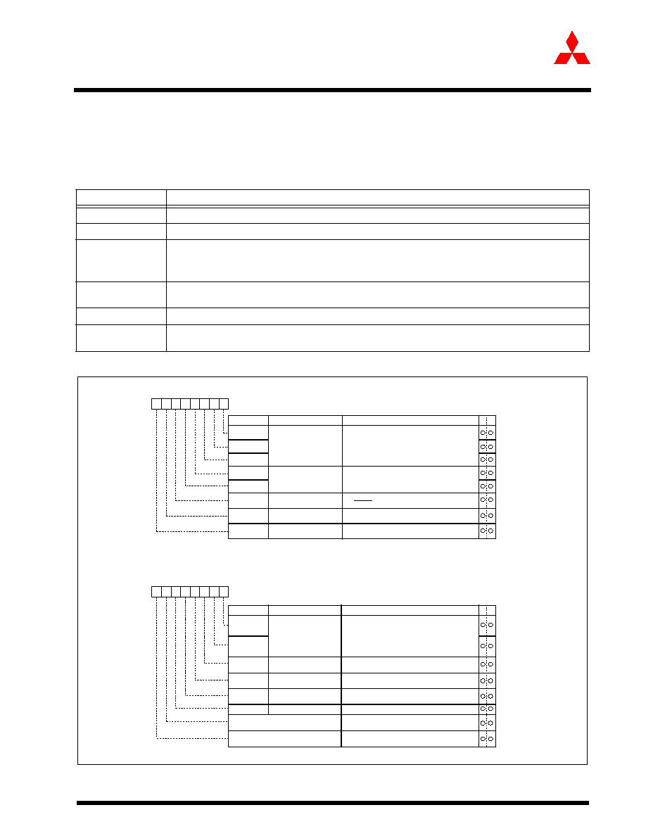
Figure 103:
A-D conversion register in single sweep mode
Table 33:
Single sweep mode specication
Item
Specication
Function
The pins selected by the A-D sweep pin select bit are used for one-by-one A-D conversion
Start condition
Writing “1” to A-D converter start ag
Stop condition
End of A-D conversion (A-D conversion start ag changes to “0”, except when external trigger is
selected)
Writing “0” to A-D conversion start ag
Interrupt request
generation timing
End of A-D conversion
Input pin
AN0 and AN1 (2 pins), AN0 to AN3 (4 pins), AN0 to AN5 (6 pins), or AN0 to AN7 (8 pins)
Reading of result
of A-D converter
Read A-D register corresponding to selected pin
A-D control register 0 (Note)
Symbol
Address
When reset
ADCON0
03D616
00000XXX2
b7
b6
b5
b4
b3
b2
b1
b0
Analog input pin
select bit
CH0
Bit symbol
Bit name
Function
CH1
CH2
A-D operation mode
select bit 0
1 0 : Single sweep mode
MD0
MD1
Trigger select bit
0 : Software trigger
1 : ADTRG trigger
TRG
ADST
A-D conversion start flag
0 : A-D conversion disabled
1 : A-D conversion started
Frequency select bit 0
0 : fAD/4 is selected
1 : fAD/2 is selected
CKS0
W
R
A-D control register 1 (Note 1)
Symbol
Address
When reset
ADCON1
03D716
0016
Bit name
Function
Bit symbol
b7
b6
b5
b4
b3
b2
b1
b0
A-D sweep pin select bit
SCAN0
SCAN1
MD2
BITS
8/10-bit mode select bit
0 : 8-bit mode
1 : 10-bit mode
VCUT
Vref connect bit
0 : Any mode other than repeat sweep mode 1
A-D operation mode
select bit 1
1 : Vref connected
W
R
1 0
Invalid in single sweep mode
0
Note 1: If the A-D control register is rewritten during A-D conversion, the conversion result
is indeterminate.
b4 b3
When single sweep and repeat sweep mode 0
are selected
0 0 : AN0, AN1 (2 pins)
0 1 : AN0 to AN3 (4 pins)
1 0 : AN0 to AN5 (6 pins)
1 1 : AN0 to AN7 (8 pins)
b1 b0
1
Note: If the A-D control register is rewritten during A-D conversion, the conversion result
is indeterminate.
Frequency select bit 1
0 : fAD/2 or fAD/4 is selected
1 : fAD is selected
CKS1
Reserved bit
Always set to
“0”
Reserved bit
Always set to
“0”
相關(guān)PDF資料 |
PDF描述 |
|---|---|
| M30245MC-XXXGP | 16-BIT, MROM, 16 MHz, MICROCONTROLLER, PQFP100 |
| M30245FCGP | 16-BIT, FLASH, 16 MHz, MICROCONTROLLER, PQFP100 |
| M30260F3VGP | 16-BIT, FLASH, 20 MHz, MICROCONTROLLER, PQFP48 |
| M30260M3A-XXXGP-U5 | 16-BIT, FLASH, 20 MHz, MICROCONTROLLER, PQFP48 |
| M30260M8A-XXXGP-U5 | 16-BIT, FLASH, 20 MHz, MICROCONTROLLER, PQFP48 |
相關(guān)代理商/技術(shù)參數(shù) |
參數(shù)描述 |
|---|---|
| M30240M2 | 制造商:MITSUBISHI 制造商全稱:Mitsubishi Electric Semiconductor 功能描述:SINGLE-CHIP 16-BIT CMOS MICROCOMPUTER |
| M30240M2-XXXFP | 制造商:MITSUBISHI 制造商全稱:Mitsubishi Electric Semiconductor 功能描述:SINGLE-CHIP 16-BIT CMOS MICROCOMPUTER |
| M30240M3 | 制造商:MITSUBISHI 制造商全稱:Mitsubishi Electric Semiconductor 功能描述:SINGLE-CHIP 16-BIT CMOS MICROCOMPUTER |
| M30240M3-XXXFP | 制造商:MITSUBISHI 制造商全稱:Mitsubishi Electric Semiconductor 功能描述:SINGLE-CHIP 16-BIT CMOS MICROCOMPUTER |
| M30240M4 | 制造商:MITSUBISHI 制造商全稱:Mitsubishi Electric Semiconductor 功能描述:SINGLE-CHIP 16-BIT CMOS MICROCOMPUTER |
發(fā)布緊急采購,3分鐘左右您將得到回復(fù)。