- 您現(xiàn)在的位置:買賣IC網(wǎng) > PDF目錄385408 > HTG2150 (Holtek Semiconductor Inc.) 8-Bit 320 Pixel LCD Microcontroller PDF資料下載
參數(shù)資料
| 型號: | HTG2150 |
| 廠商: | Holtek Semiconductor Inc. |
| 英文描述: | 8-Bit 320 Pixel LCD Microcontroller |
| 中文描述: | 8位微控制器320像素LCD |
| 文件頁數(shù): | 15/49頁 |
| 文件大?。?/td> | 316K |
| 代理商: | HTG2150 |
第1頁第2頁第3頁第4頁第5頁第6頁第7頁第8頁第9頁第10頁第11頁第12頁第13頁第14頁當前第15頁第16頁第17頁第18頁第19頁第20頁第21頁第22頁第23頁第24頁第25頁第26頁第27頁第28頁第29頁第30頁第31頁第32頁第33頁第34頁第35頁第36頁第37頁第38頁第39頁第40頁第41頁第42頁第43頁第44頁第45頁第46頁第47頁第48頁第49頁

HTG2150
15
July 24, 2000
Preliminary
Register
Bit No.
Label
Function
INTCH
0
ET2I
Controls the Timer 2 interrupt
(1=enable; 0=disable)
1
ET3I
Controls the Timer 3 interrupt
(1=enable; 0=disable)
2
PWMI
PWM D/A interrupt (1=enable; 0=disable)
3
Should be set as 0 always
4
T2F
Internal Timer 2 request flag
(1=active; 0=inactive)
5
T3F
Internal Timer 3 request flag
(1=active; 0=inactive)
6
PWMF
PWM D/A flag (1=active; 0=inactive)
7
Should be set as 0 always
INTCH register
No.
Interrupt Source Priority Vector
a
External interrupt
1
04H
b
Timer counter 0
overflow
2
08H
d
Timer 2 overflow
4
10H
e
Timer 3 overflow
5
14H
f
PWM D/A interrupt
6
18H
The timer counter 0 and Timer 2/3 interrupt re-
quest flag (T0F/T2F/T3F), External interrupt re-
quest flag (EIF), PWM D/A interrupt request flag
(PWMF),EnableTimer0/2/3bit(ET0I/ET2I/ET3I)
, Enable PWM D/A interrupt (PWMI), Enable ex-
ternal interrupt bit (EEI) and Enable master in-
terrupt bit (EMI) constitute an interrupt control
register (INTC/INTCH) which is located at
0BH/1EH in the data memory. EMI, EEI, ET0I,
ET2I, ET3I, PWMI are used to control the en-
abling/disabling of interrupts. These bits prevent
the requested interrupt from being serviced. Once
the interrupt request flags (T0F, T2F, T3F, EIF,
PWMF) are set, they will remain in the
INTC/INTCHregisteruntiltheinterruptsareser-
viced or cleared by a software instruction.
It is recommended that a program does not use
the
CALL subroutine
subroutine. Interrupts often occur in an unpre-
dictable manner or need to be serviced immedi-
atelyinsomeapplications.Ifonlyonestackisleft
within the interrupt
and enabling the interrupt is not well controlled,
the CALLsubroutine shouldnotoperateinthein-
terrupt subroutine as it will damage the original
control sequence.
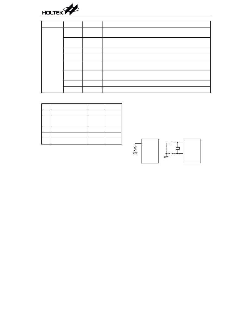
Oscillator configuration
There are two oscillator circuits in the HTG2150.
The RC oscillator signal provides the internal
system clock. The HALT mode stops the system
oscillator and ignores any external signal to
conserve power. Only the RC oscillator is de-
signed to drive the internal system clock. The
RTC oscillator provides the Timer 3 and LCD
driver clock source.
The RC oscillator needs an external resistor
connected between OSCI and VSS. The resis-
tance value must range from 50k
However, the frequency of the oscillation may
vary with V
DD
, temperature and the chip itself
duetoprocessvariations.Itis,therefore,notsuit-
able for timing sensitive operations where accu-
rate oscillator frequency is desired.
to 400k .
*
7 7
. , 4 5 6
*7 7
System and RTC oscillator
相關(guān)PDF資料 |
PDF描述 |
|---|---|
| HTG2190 | 8-Bit 1024 Pixel LCD Microcontroller |
| HTIP117D | PNP EPITAXIAL PLANAR TRANSISTOR |
| HTM1505 | RELATIVE HUMIDITY AND TEMPERATURE MODULE |
| HTM2500 | RELATIVE HUMIDITY/ TEMPERATURE MODULE |
| HTS2010SMD | TEMPERATURE AND RELATIVE HUMIDITY SENSOR |
相關(guān)代理商/技術(shù)參數(shù) |
參數(shù)描述 |
|---|---|
| HTG2150_02 | 制造商:HOLTEK 制造商全稱:Holtek Semiconductor Inc 功能描述:8-Bit 320 Pixel Dot Matrix LCD MCU Series |
| HTG2170 | 制造商:未知廠家 制造商全稱:未知廠家 功能描述:8-Bit Microcontroller |
| HTG2190 | 制造商:HOLTEK 制造商全稱:Holtek Semiconductor Inc 功能描述:8-Bit 1024 Pixel Dot Matrix LCD MCU Series |
| HTG2190_02 | 制造商:HOLTEK 制造商全稱:Holtek Semiconductor Inc 功能描述:8-Bit 1024 Pixel Dot Matrix LCD MCU Series |
| HTG3110 | 制造商:未知廠家 制造商全稱:未知廠家 功能描述:Speech Synthesizer |
發(fā)布緊急采購,3分鐘左右您將得到回復(fù)。