- 您現(xiàn)在的位置:買賣IC網(wǎng) > PDF目錄385408 > HTG2150 (Holtek Semiconductor Inc.) 8-Bit 320 Pixel LCD Microcontroller PDF資料下載
參數(shù)資料
| 型號: | HTG2150 |
| 廠商: | Holtek Semiconductor Inc. |
| 英文描述: | 8-Bit 320 Pixel LCD Microcontroller |
| 中文描述: | 8位微控制器320像素LCD |
| 文件頁數(shù): | 14/49頁 |
| 文件大小: | 316K |
| 代理商: | HTG2150 |
第1頁第2頁第3頁第4頁第5頁第6頁第7頁第8頁第9頁第10頁第11頁第12頁第13頁當(dāng)前第14頁第15頁第16頁第17頁第18頁第19頁第20頁第21頁第22頁第23頁第24頁第25頁第26頁第27頁第28頁第29頁第30頁第31頁第32頁第33頁第34頁第35頁第36頁第37頁第38頁第39頁第40頁第41頁第42頁第43頁第44頁第45頁第46頁第47頁第48頁第49頁

HTG2150
14
July 24, 2000
Preliminary
rupt request flag is recorded. If a certain inter-
rupt needs servicing within the service routine,
the programmer may set the EMI bit and the
corresponding bit of the INTC to allow interrupt
nesting. If the stack is full, the interrupt request
will not be acknowledged, even if the related in-
terruptisenabled,untiltheSPisdecremented.If
immediate service is desired, the stack must be
prevented from becoming full.
All these kinds of interrupt have a wake-up ca-
pability. As an interrupt is serviced, a control
transferoccursbypushingtheprogramcounter
and A13 bit onto the stack followed by a branch
to subroutines at specified locations in the pro-
gram memory. Only the program counter and
A13 bit are pushed onto the stack. If the con-
tents of the register and Status register
(STATUS) are altered by the interrupt service
program which corrupt the desired control se-
quence, the contents should be saved first.
External interrupt is triggered by a high to low
transition of INT and the related interrupt re-
quest flag (EIF; bit 4 of INTC) will be set. When
the interrupt is enabled, and the stack is not
full and the external interrupt is active, a sub-
routine call to location 04H will occur. The in-
terrupt request flag (EIF) and EMI bits will be
cleared to disable other interrupts.
The internal timer counter 0 interrupt is ini-
tialized by setting the timer counter 0 interrupt
request flag (T0F; bit 5 of INTC), resulting from
a timer 0 overflow. When the interrupt is en-
abled, and the stack is not full and the T0F bit
is set, a subroutine call to location 08H will oc-
cur. The related interrupt request flag (T0F)
will be reset and the EMI bit cleared to disable
further interrupts.
The Timer 2/3 interrupts are operated in the
same manner as timer 0. While ET2I/ET3I and
T2F/T3F are the related control bits and the re-
lated request flags of TMR2/TMR3, which lo-
cate at bit0/bit1 and bit4/bi5 of the INTCH
respectively.
During the execution of an interrupt subroutine,
other interrupt acknowledgments are held until
the RETI instruction is executed or the EMI bit
andtherelatedinterruptcontrolbitaresetto1(if
the stack is not full). To return from the interrupt
subroutine, the RET or RETI instruction may be
invoked.RETIwillsettheEMIbittoenableanin-
terrupt service, but RET will not.
Interrupts occurring in the interval between
the rising edges of two consecutive T2 pulses,
will be serviced on the latter of the two T2
pulses, if the corresponding interrupts are en-
abled. In the case of simultaneous requests the
priorities applied are shown in the following ta-
ble. These can be masked by resetting the EMI
bit.
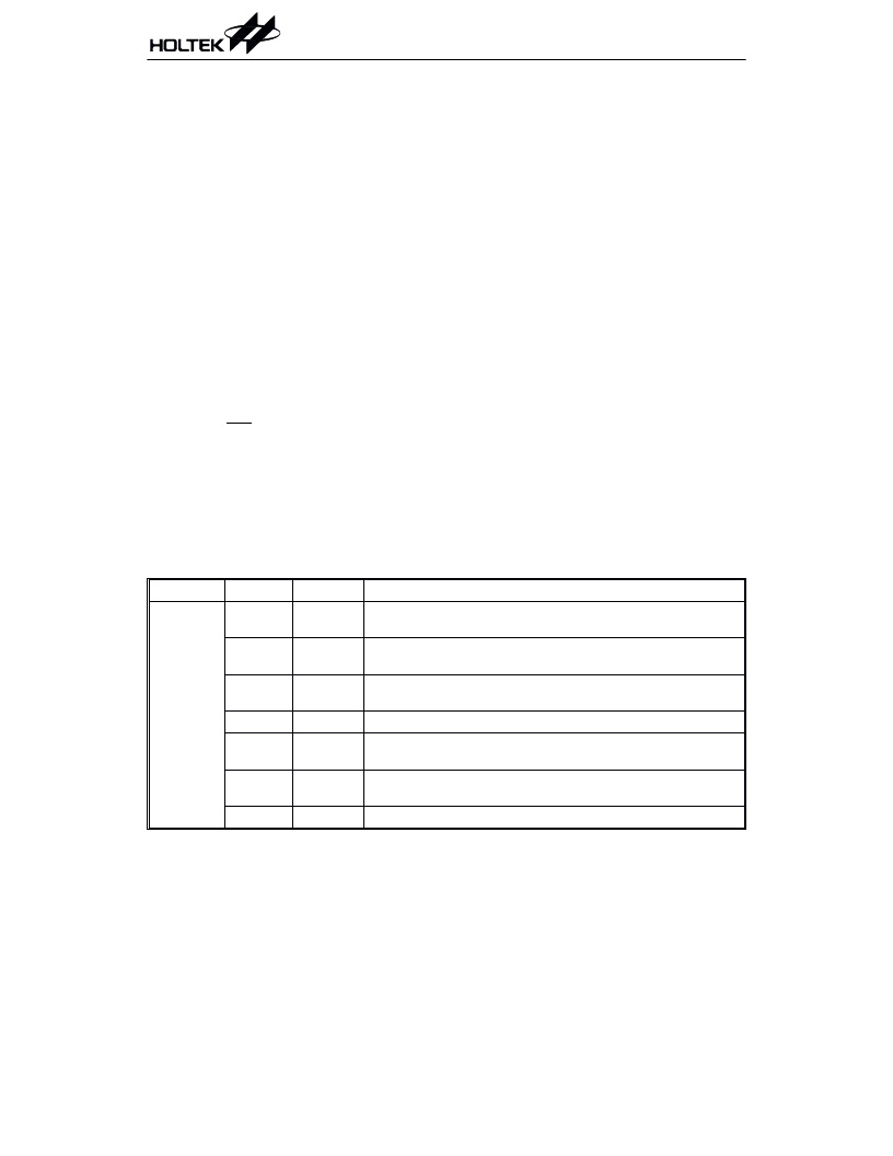
Register
Bit No.
Label
Function
INTC
0
EMI
Controls the (global) interrupt
(1=enable; 0=disable)
1
EEI
Controls the external interrupt
(1=enable; 0=disable)
2
ET0I
Controls the timer counter 0 interrupt
(1=enable; 0=disable)
3
Unused bit
4
EIF
External interrupt request flag
(1=active; 0=inactive)
5
T0F
Internal timer counter 0 request flag
(1=active; 0=inactive)
6, 7
Unused bit
INTC register
相關(guān)PDF資料 |
PDF描述 |
|---|---|
| HTG2190 | 8-Bit 1024 Pixel LCD Microcontroller |
| HTIP117D | PNP EPITAXIAL PLANAR TRANSISTOR |
| HTM1505 | RELATIVE HUMIDITY AND TEMPERATURE MODULE |
| HTM2500 | RELATIVE HUMIDITY/ TEMPERATURE MODULE |
| HTS2010SMD | TEMPERATURE AND RELATIVE HUMIDITY SENSOR |
相關(guān)代理商/技術(shù)參數(shù) |
參數(shù)描述 |
|---|---|
| HTG2150_02 | 制造商:HOLTEK 制造商全稱:Holtek Semiconductor Inc 功能描述:8-Bit 320 Pixel Dot Matrix LCD MCU Series |
| HTG2170 | 制造商:未知廠家 制造商全稱:未知廠家 功能描述:8-Bit Microcontroller |
| HTG2190 | 制造商:HOLTEK 制造商全稱:Holtek Semiconductor Inc 功能描述:8-Bit 1024 Pixel Dot Matrix LCD MCU Series |
| HTG2190_02 | 制造商:HOLTEK 制造商全稱:Holtek Semiconductor Inc 功能描述:8-Bit 1024 Pixel Dot Matrix LCD MCU Series |
| HTG3110 | 制造商:未知廠家 制造商全稱:未知廠家 功能描述:Speech Synthesizer |
發(fā)布緊急采購,3分鐘左右您將得到回復(fù)。