- 您現(xiàn)在的位置:買賣IC網(wǎng) > PDF目錄385403 > HT82A832R (Holtek Semiconductor Inc.) Basic USB Phone OTP MCU PDF資料下載
參數(shù)資料
| 型號: | HT82A832R |
| 廠商: | Holtek Semiconductor Inc. |
| 英文描述: | Basic USB Phone OTP MCU |
| 中文描述: | 檢察官辦公室的基本USB電話單片機 |
| 文件頁數(shù): | 29/51頁 |
| 文件大小: | 345K |
| 代理商: | HT82A832R |
第1頁第2頁第3頁第4頁第5頁第6頁第7頁第8頁第9頁第10頁第11頁第12頁第13頁第14頁第15頁第16頁第17頁第18頁第19頁第20頁第21頁第22頁第23頁第24頁第25頁第26頁第27頁第28頁當(dāng)前第29頁第30頁第31頁第32頁第33頁第34頁第35頁第36頁第37頁第38頁第39頁第40頁第41頁第42頁第43頁第44頁第45頁第46頁第47頁第48頁第49頁第50頁第51頁
HT82A832R
Rev. 1.00
29
July 18, 2006
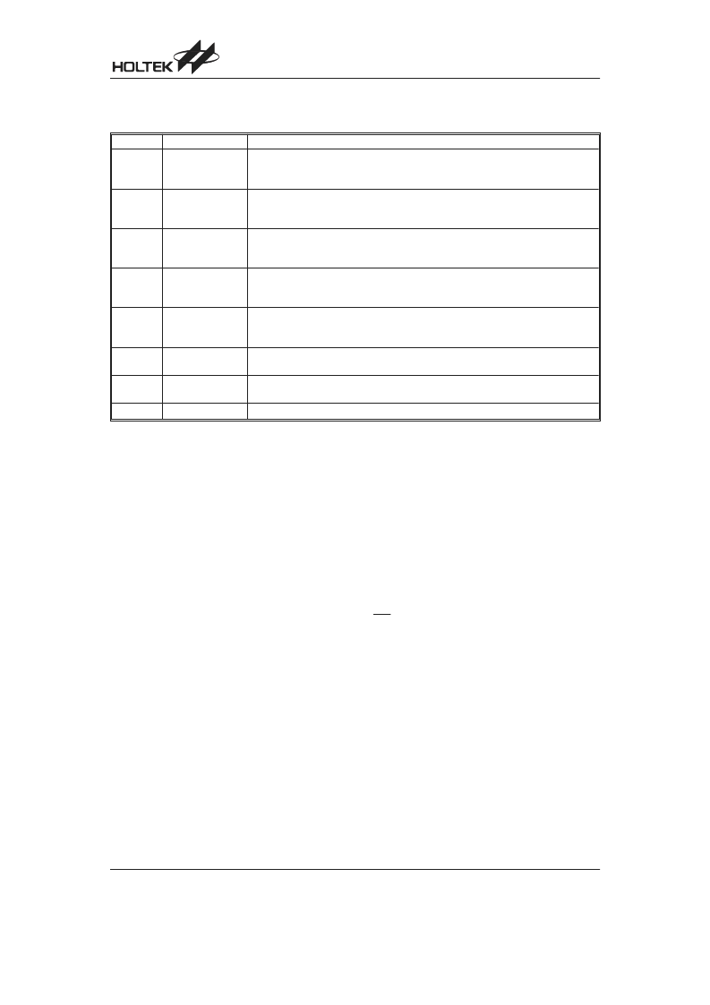
Mode Control
The MODE_CTRL register is used to control DAC and ADC operation mode and SPI function.
Bit No.
Label
Functions
0
DA_L_ENB
DAC enable/disable control (left channel)
1= DAC Left Channel disable
0= DAC Left Channel enable (default)
1
DA_R_ENB
DAC enable/disable control (right channel)
1= DAC Right Channel disable
0= DAC Right Channel enable (default)
2
AD_ENB
ADC enable/disable control
1= ADC power down
0= ADC power on (default)
3
PLAY_MODE
DAC play mode control
1= 8kHz/16-bit
0= 48kHz/16-bit (default)
4
SIO_CPOL
There are three bits used to control the mode of SPI operation.
1= clock polarity rising edge
0= clock polarity falling edge (default)
5
SIO_WCOL
1= WCOL bit of SBCR register enable
0= WCOL bit of SBCR register disable (default)
6
SIO_CSEN
1= CSEN bit of SBCR register enable
0= CSEN bit of SBCR register disable (Default)
7
Undefined bit, read as 0
MODE_CTRL (34H) Register
SPI Usage Example
SPI_Test:
clr
set
clr
;Master Mode, SCLK=fSIO
clr
M1
clr
M0
;--------------
clr
CKS
clr
TRF
clr
TRF_INT
set
MLS
set
CSEN
set
SBEN
if POLLING_MODE
clr
ESII
;WRITE INTO "WRITE ENABLE" INSTRUCTION
MOV
A,OP_WREN
MOV
SBDR,A
$0:
snz
TRF
jmp
$0
clr
TRF
else
set
ESII
;WRITE INTO "WRITE ENABLE" INSTRUCTION
MOV
A,OP_WREN
MOV
SBDR,A
$0:
snz
TRF_INT
jmp
$0
clr
TRF_INT
endif
UCC.@UCC_SYSCLK
SIO_CSEN
SIO_CPOL
;12MHz SYSCLK
;SPI Chip Select Function Enable
;falling edge change data
;fSIO=fsys/2
;clear TRF flag
;clear Interrupt SPI flag
;MSB shift first
;Chip Select Enable
;SPI Enable, SCS will go low
;SPI Interrupt Disable
;SPI Interrupt Enable
;set at SPI Interrupt
相關(guān)PDF資料 |
PDF描述 |
|---|---|
| HT82A850R | Audio MCU |
| HT82A851R | USB Audio MCU |
| HT82J30A | 16 Channel A/D MCU with SPI Interface |
| HT82J30R | 16 Channel A/D MCU with SPI Interface |
| HT82J927A | USB Gamepad |
相關(guān)代理商/技術(shù)參數(shù) |
參數(shù)描述 |
|---|---|
| HT82A832R_07 | 制造商:HOLTEK 制造商全稱:Holtek Semiconductor Inc 功能描述:USB Audio MCU |
| HT82A834R | 制造商:HOLTEK 制造商全稱:Holtek Semiconductor Inc 功能描述:USB Audio MCU |
| HT82A836R | 制造商:HOLTEK 制造商全稱:Holtek Semiconductor Inc 功能描述:USB Audio MCU |
| HT82A850R | 制造商:HOLTEK 制造商全稱:Holtek Semiconductor Inc 功能描述:Audio MCU |
| HT82A851R | 制造商:HOLTEK 制造商全稱:Holtek Semiconductor Inc 功能描述:USB Audio MCU |
發(fā)布緊急采購,3分鐘左右您將得到回復(fù)。